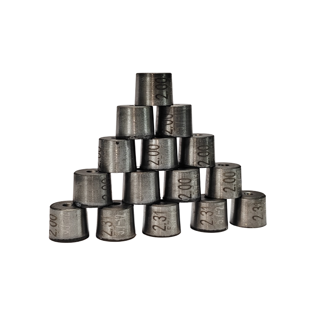
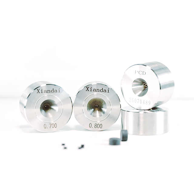
Carbide Drawing Dies are manufactured from high-strength and wear-resistant tungsten carbide to provide a combination of surface finish, wear resistance, impact resistance and practical serviceability for metal drawing operations.
Compared with diamond drawing dies, tungsten carbide dies offer greater toughness and impact resistance, making them particularly suitable for coarse and intermediate drawing or operating conditions involving higher mechanical loads.
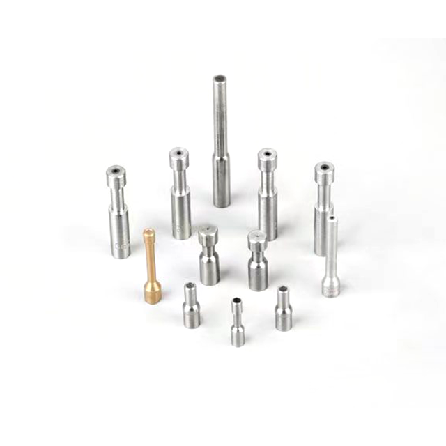
Modern Diamond offers multiple carbide drawing die configurations, including American R Series, Japanese W Series and Chinese Standard Series, as well as customized dies for different wire, rod and tube drawing requirements.
The die bore can also be reconditioned multiple times when the condition and required finished size allow, helping extend the practical utilization of the die.
The high-hardness carbide working material provides good wear resistance under continuous metal drawing conditions, helping maintain the die profile and drawing performance.
Tungsten carbide provides greater toughness and impact resistance than diamond die materials, making it suitable for demanding drawing conditions as well as coarse and intermediate wire drawing.
Carbide drawing dies provide good resistance to acidic and alkaline environments and can adapt to drawing processes using wet lubrication.
Compared with natural diamond and PCD drawing dies, carbide dies provide lower material, manufacturing and maintenance costs, making them a practical choice for large-volume industrial drawing applications.
Depending on bore condition and required finished size, the die hole can be repaired and reconditioned multiple times, allowing continued use for suitable drawing specifications.
American R Series, Japanese W Series and Chinese Standard Series are available to match different drawing machines and die holders. Custom specifications can also be produced according to specific processing requirements.
Parameter | Specification |
|---|---|
Product Type | Carbide Wire Drawing Die |
Material | Tungsten Carbide |
Drawing Range | 0.1–45 mm |
Main Recommended Range | ≥0.2 mm |
Available Series | American R Series / Japanese W Series / Chinese Standard Series |
Die Case OD | Φ28 / Φ42 / Φ66 mm and Other Standard Sizes |
Drawing Products | Wire / Rod / Tube |
Main Materials | Carbon Steel / Stainless Steel / Copper / Aluminum |
Special Applications | Tungsten / Molybdenum with Selected Carbide Grades |
Custom Sizes | Available |
Bore Reconditioning | Available Depending on Bore Condition & Required Size |
The overall drawing range is 0.1–45 mm, with wire above 0.2 mm representing the main application range for carbide dies. For ultra-fine wire below 0.2 mm, PCD drawing dies are generally recommended to reduce excessive carbide die wear.
Modern Diamond provides different die case sizes to accommodate different drawing ranges and production requirements.
Die Case OD | Die Case Height | Die Case Bore Range | Drawing Range |
|---|---|---|---|
Φ28 mm | 14 mm | Φ10–Φ16 mm | 0.1–5.5 mm |
Φ42 mm | 15 / 28 mm | Φ20–Φ25 mm | 6–20 mm |
Φ66 mm | 35 mm | Φ30–Φ40 mm | Above 20 mm |
These specifications provide reference configurations for different wire diameter ranges. Custom die dimensions can be supplied according to the drawing machine, die holder and required finished product.
Japanese W Series sizes are available for customers using corresponding JIS-type die dimensions and drawing equipment.
JIS Type | Die Blank Dia. (mm) | Die Blank Height (mm) | Die Case Dia. (mm) | Die Case Height (mm) |
|---|---|---|---|---|
W101 | 6 | 4 | 24 | 7 |
W102 | 9 | 6 | 24 | 12 |
W103 | 12 | 8 | 30 | 15 |
W104 | 15 | 10 | 42 | 20 |
W105 | 20 | 14 | 55 | 24 |
W106 | 25 | 18 | 60 | 28 |
W107 | 30 | 22 | 70 | 35 |
W108 | 35 | 25 | 85 | 40 |
W109 | 40 | 27 | 100 | 45 |
W110 | 50 | 30 | 125 | 50 |
W111 | 60 | 35 | 145 | 60 |
W112 | 70 | 40 | 175 | 70 |
W113 | 80 | 45 | 195 | 80 |
W114 | 90 | 50 | 215 | 90 |
W115 | 100 | 50 | 230 | 90 |
W116 | 110 | 50 | 230 | 90 |
W117 | 120 | 55 | 250 | 100 |
W118 | 130 | 55 | 275 | 100 |
W119 | 140 | 60 | 295 | 110 |
W120 | 150 | 60 | 315 | 110 |
Chinese Standard Series provides multiple die blank and die case dimensions for different drawing equipment and applications.
Type | Die Blank Dia. (mm) | Die Blank Height (mm) | Die Case Dia. (mm) | Die Case Height (mm) |
|---|---|---|---|---|
B | 13 | 10 | 30 | 16 |
D | 16 | 14 | 32 | 20 |
G | 22 | 18 | 40 | 26 |
H | 30 | 21 | 66 | 35 |
K | 40 | 25 | 95 | 40 |
L | 50 | 28 | 95 | 48 |
M | 60 | 35 | 114 | 60 |
N | 75 | 35 | 114 | 70 |
O | 90 | 35 | 145 | 70 |
American R Series carbide drawing dies are available in standard inch dimensions for compatible drawing machines and die holders.
Type | Die Blank Dia. (in) | Die Blank Height (in) | Die Case Dia. (in) | Die Case Height (in) |
|---|---|---|---|---|
R2 | 0.325 | 0.33 | 1 | 9/16 |
R3 | 0.45 | 0.38 | 1-1/2 | 3/4 |
R4 | 0.5 | 0.45 | 1-1/2 | 7/8 |
R5 | 0.625 | 0.6 | 1-1/2 | 7/8 |
R6 | 0.71 | 0.7 | 2 | 1-1/8 |
R7 | 0.768 | 0.768 | 3 | 1-3/8 |
R8 | 1 | 0.82 | 3 | 1-3/4 |
R9 | 1.187 | 0.82 | 3 | 1-3/4 |
R10 | 1.5 | 1 | 3 | 2 |
R11 | 1.83 | 1.25 | 4 | 2-1/4 |
R12 | 2.185 | 1.375 | 4 | 2-3/8 |
R14 | 2.56 | 1.375 | 6 | 2-1/2 |
R15 | 3 | 1.375 | 6 | 2-1/2 |
R16 | 3.5 | 1.375 | 7 | 2-1/2 |
R17 | 4 | 1.5 | 7 | 2-1/2 |
R18 | 5.5 | 2.125 | 9 | 4-1/2 |
R19 | 6.5 | 2.125 | 11 | 4-1/2 |
Carbide Drawing Dies can be used across ferrous and non-ferrous metal drawing applications.
The wear resistance, toughness and impact resistance of tungsten carbide make it suitable for carbon steel wire drawing, particularly in coarse and intermediate drawing stages.
Carbide drawing dies can be configured for stainless steel drawing according to the wire diameter, reduction requirements and production conditions.
Carbide dies provide a cost-effective solution for conventional copper wire drawing, especially for wire sizes where impact resistance and production economy are important.
Tungsten carbide drawing dies are suitable for aluminum wire drawing and can be configured according to the required incoming and finished diameters.
In addition to wire drawing, carbide dies can be produced for metal rod and tube drawing applications according to the required dimensions and die geometry.
Selected special carbide grades can also be used for drawing high-melting-point metals such as tungsten and molybdenum. The appropriate grade and die configuration should be confirmed according to the actual application.
The performance of a Carbide Drawing Die depends not only on carbide material properties but also on the geometry of the internal die profile.
A typical drawing die includes an entrance zone, lubrication zone, reduction zone, bearing zone and exit zone. Each section performs a different function during metal drawing.
See how precision machining is used to form the internal profile of a tungsten carbide drawing die for stable wire, rod and tube drawing.
The entrance zone guides the wire, rod or other workpiece smoothly into the die and helps maintain alignment before deformation begins.
For reference, softer wires such as copper and aluminum typically use entrance angles of approximately 60°–80°, while harder wire materials may use approximately 45°–60°.
The lubrication zone helps introduce and retain lubricant before the material enters the primary deformation area.
A typical reference lubrication angle is approximately 30°–35°, although the final design should be matched to the actual drawing process.
The reduction zone is where the main plastic deformation occurs.
For softer materials such as copper and aluminum, a typical reference reduction angle is approximately 16°–18°. For harder wire materials, approximately 12°–14° may be used as a reference.
The final angle should be determined according to material properties, reduction ratio and drawing conditions rather than applying one angle to every application.
The bearing zone controls the final drawn size, dimensional consistency, roundness and surface quality.
A typical reference bearing length is approximately 0.2D–0.8D, depending on wire diameter and drawing requirements.
The exit zone provides a smooth path for the finished material to leave the die and helps minimize unwanted contact with the die edge.
Reduction angle and bearing length are two important parameters affecting drawing force, dimensional stability, friction, heat generation and die wear.
An excessively large reduction angle can shorten the deformation zone and increase localized deformation and heat.
An excessively small reduction angle can extend the deformation path, increasing contact friction and drawing force.
Similarly, an excessively long bearing zone increases contact and friction, while an excessively short bearing zone may not provide sufficient dimensional control.
The die geometry should therefore be configured as a complete system according to the actual material and drawing process rather than selecting each parameter independently.
One of the primary advantages of tungsten carbide dies is their suitability for coarse and intermediate drawing.
Compared with ultra-fine precision wire applications, these drawing stages place greater emphasis on:
Impact Resistance
Mechanical Strength
Wear Resistance
Production Stability
Cost Efficiency
Reconditioning Capability
For this reason, carbide dies are particularly suitable for wire sizes above 0.2 mm, while ultra-fine wire below 0.2 mm is generally better matched with PCD drawing dies according to the supplied product information.
Carbide and PCD Drawing Dies have different strengths and should be selected according to the wire size and production requirements.
Comparison | Carbide Drawing Dies | PCD Drawing Dies |
|---|---|---|
Impact Resistance | Strong | Lower than Carbide |
Wear Resistance | High | Very High |
Cost | More Economical | Higher |
Main Wire Range | Especially Suitable Above 0.2 mm | Better Option for Finer Wire |
Coarse Drawing | Recommended | Application-Dependent |
Intermediate Drawing | Recommended | Available |
Ultra-Fine Wire | Not Preferred | Recommended |
Bore Reconditioning | Available | Application-Dependent |
If the application involves coarse or intermediate drawing, larger wire sizes, demanding operating conditions or cost-sensitive mass production, Carbide Drawing Dies are often the practical choice.
For ultra-fine wire below 0.2 mm or applications requiring higher wear resistance, PCD Drawing Dies should be considered.
A closer look at the machining equipment used in the production of tungsten carbide drawing dies.
Different wire materials, drawing machines and finished dimensions require different die configurations.
Modern Diamond can provide customized Carbide Drawing Dies according to your actual drawing process.
For accurate die selection, please provide:
Material
Carbon steel, stainless steel, copper, aluminum or other metal.
Product Type
Wire, rod or tube.
Incoming Diameter
Required Finished Diameter
Reduction Requirement
Drawing Machine / Die Holder
Required Die Series
R Series, W Series, Chinese Standard Series or custom specification.
Dimensional & Surface Requirements
Based on this information, the appropriate die size, bore geometry and carbide die configuration can be selected for your drawing process.
Send Your Drawing Requirements
Carbide dies cover a broad 0.1–45 mm drawing range.
For standard configurations:
0.1–5.5 mm: Φ28 mm die case
6–20 mm: Φ42 mm die case
Above 20 mm: Φ66 mm die case
The final size should still be confirmed according to the actual equipment and die holder.
Different materials have different hardness and deformation characteristics.
Carbon steel and stainless steel require different drawing conditions from copper and aluminum, so reduction geometry and process parameters should be matched accordingly.
For coarse and intermediate drawing, tungsten carbide provides a useful combination of toughness, wear resistance and cost efficiency.
For ultra-fine wire, especially below 0.2 mm, PCD should also be evaluated.
Customers using existing drawing machines can select from American R Series, Japanese W Series or Chinese Standard Series, or provide their required dimensions for customization.
If die reconditioning is part of your production strategy, the original die specification and available bore material should be considered so that the die can potentially be reused for a larger finished size after wear.
A Carbide Drawing Die is a metal drawing tool that uses high-strength, wear-resistant carbide as the working material. It is used to control and reduce the cross-section of wire, rod or tube as the material passes through the die.
The available drawing range is approximately 0.1–45 mm. Wire above 0.2 mm represents the main application range for carbide dies.
They can be used for ferrous metals such as carbon steel and stainless steel, as well as non-ferrous metals such as copper and aluminum. Selected special carbide grades can also be configured for tungsten and molybdenum applications.
Yes. In addition to wire drawing dies, carbide dies can be configured for wire, rod and tube drawing according to the required dimensions and drawing conditions.
Available standard systems include American R Series, Japanese W Series and Chinese Standard Series, covering a broad range of die blank and die case dimensions.
Carbide dies can cover wire diameters down to approximately 0.1 mm, but for ultra-fine wire below 0.2 mm, PCD drawing dies are generally recommended to reduce excessive carbide die wear.
Yes. One of the advantages identified for these carbide drawing dies is the ability to recondition the die bore multiple times where the remaining die condition and required finished diameter permit.
Yes. In addition to standard R, W and Chinese Standard Series dimensions, custom die sizes can be produced according to the customer's drawing machine, die holder, material and required finished dimensions.
Please provide your material, wire/rod/tube type, incoming diameter, finished diameter, drawing machine or die holder dimensions, required die series and other dimensional requirements.