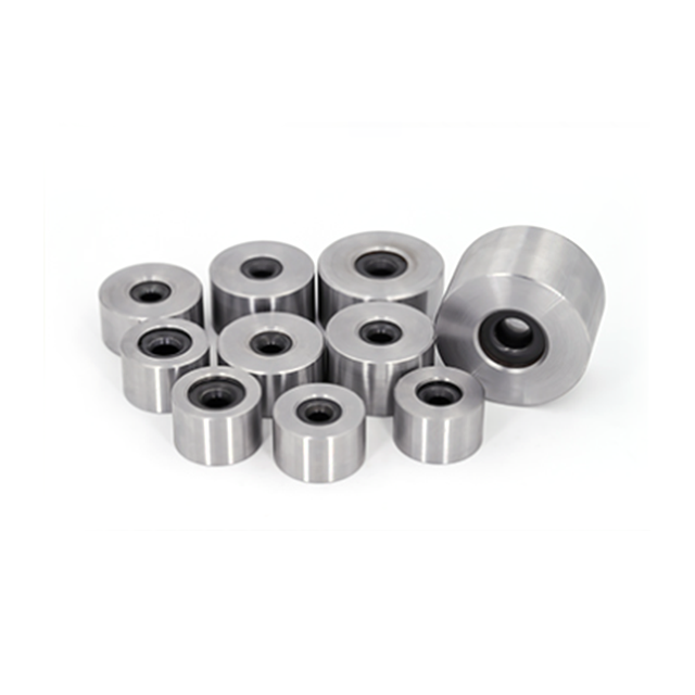
Nano-coated drawing dies combine precision die geometry with a high-hardness diamond coating to support stable metal wire drawing under demanding operating conditions.
The diamond coating reaches a hardness of HV ≥4000 kg/mm², while the polished coated surface can achieve a surface roughness typically ≤100 nm. Specialized substrate pretreatment is used to improve coating-to-substrate adhesion, with compression resistance reaching up to 1.5 kN according to the supplied technical specifications.
Unlike a standard die with fixed geometry, each coated wire drawing die can be matched to specific wire materials, diameters, reduction ratios and equipment conditions.
The diamond coating has a hardness of HV ≥4000 kg/mm², providing a wear-resistant working surface for continuous wire drawing applications.
The coating consists of a micron-scale diamond base layer and a nano-scale diamond surface layer, combining coating durability with a finely finished working surface.
After polishing, the coated surface can achieve a surface roughness typically ≤100 nm, helping reduce friction between the wire and die surface during drawing.
Outer diameter, die height, hole diameter, reduction angle and bearing length can be selected or customized according to different wire drawing requirements.
Actual die parameters can be matched according to wire material, reduction ratio and equipment operating conditions rather than relying on a single standard configuration.
Parameter | Specification |
|---|---|
Product Type | Nano-Coated Wire Drawing Die |
Coating Type | Diamond Coating |
Coating Structure | Micron-Scale Diamond Base Layer + Nano-Scale Diamond Surface Layer |
Outer Diameter (D) | 13 mm, 16 mm, 19 mm, 21 mm or Customized |
Die Height (H) | 10 mm, 13 mm, 17 mm, 20 mm or Customized |
Hole Diameter | Typically 0.5–50 mm, Depending on Application |
Reduction Angle (C) | 10°, 12°, 14°, 16°, 18° or Customized |
Bearing Length | Typically 4.5 mm or Customized |
Working Area Angle Tolerance | Typically ±1° |
Coating Hardness | HV ≥4000 kg/mm² |
Surface Roughness | Typically ≤100 nm After Polishing |
Compression Resistance | Up to 1.5 kN |
Outer Sleeve Size | 0.3D / 0.35D / 0.4D Where Applicable |
Customization | Available |
Note: Typical outer diameters include 13 mm, 16 mm, 19 mm and 21 mm, while common die heights include 10 mm, 13 mm, 17 mm and 20 mm. Reduction angles such as 10°, 12°, 14°, 16° and 18° can be selected according to wire material and reduction ratio.
The specifications above are typical reference values. Actual die dimensions and geometry should be matched to the wire material, wire diameter, reduction ratio, drawing equipment and required finished-wire accuracy.
Precision of the die bore directly affects finished wire dimensions and drawing consistency. Hole diameter tolerance and roundness tolerance should therefore be controlled according to the required bore size.
Hole Diameter | Hole Diameter Tolerance | Roundness Tolerance |
|---|---|---|
≤ 0.040 mm | ±0.0003 mm | ±0.0002 mm |
0.041–0.099 mm | ±0.0005 mm | ±0.0003 mm |
0.100–0.499 mm | ±0.001 mm | According to Required Specification |
Larger Diameters | Adjusted According to Bore Size | According to Required Specification |
Working Area Angle Tolerance: Typically ±1°
For larger bore sizes, tolerances should be determined according to the required die specification and finished-wire accuracy rather than applying the same tolerance to all diameters.
The performance of a nano-coated drawing die depends on both the coating structure and the quality of the coated working surface.
Coating Parameter | Specification |
|---|---|
Coating Hardness | HV ≥4000 kg/mm² |
Coating Thickness | Micro/Nano Scale |
Coating Structure | Micron-Scale Diamond Base + Nano-Scale Diamond Surface |
Surface Roughness | Typically ≤100 nm After Polishing |
Coating Adhesion | Enhanced Through Specialized Substrate Pretreatment |
Compression Resistance | Up to 1.5 kN |
The micro/nano diamond coating structure combines a durable diamond base layer with a finely finished nano-scale surface layer. The polished surface provides low roughness, while specialized pretreatment helps strengthen the bond between the coating and substrate.
Coating performance is only one part of a high-performance drawing die. The internal die profile also directly affects wire deformation, drawing force, dimensional accuracy, surface quality and die wear.
A typical drawing die profile consists of five functional zones:
The entrance zone guides the wire smoothly into the die and helps align the wire with the center of the die. Proper entrance geometry also supports lubricant entry and helps reduce initial friction and surface damage.
The lubrication zone helps establish a stable lubricant film before the wire enters the high-stress deformation area.
Effective lubrication helps reduce friction and heat accumulation in the working area and can contribute to more stable drawing conditions.
The reduction zone is the primary deformation area of the drawing die. The wire cross-section is progressively reduced here until it approaches the required finished diameter.
Reduction angle and reduction-zone length influence metal flow, drawing force, deformation uniformity, surface condition and die wear.
An excessively large reduction angle can make deformation more concentrated, while an excessively small angle can extend the deformation path and increase friction and heat.
The bearing zone controls the final wire diameter and helps maintain dimensional consistency and surface quality.
Bearing length must balance dimensional stability and friction. A bearing section that is too long can increase contact friction and heat, while one that is too short may reduce dimensional stability.
For coated drawing dies, a typical bearing length may be around 4.5 mm, while custom lengths can be produced according to actual drawing requirements.
The exit zone provides a smooth path for the finished wire to leave the die. Proper exit geometry helps reduce unwanted contact with the die edge and supports stable wire exit.
The reduction angle, bearing length and reduction-zone length are three important geometric factors affecting wire drawing performance.
The reduction angle determines how the wire undergoes plastic deformation.
If the angle is too large, deformation may become concentrated and increase stress. If the angle is too small, the deformation path becomes longer, potentially increasing friction and heat.
Typical coated drawing die reduction angles include:
10° / 12° / 14° / 16° / 18°
The final angle should be selected according to wire material and reduction ratio.
The bearing zone provides final dimensional control after the wire passes through the reduction zone.
For nano-coated drawing dies, a typical bearing length is 4.5 mm, although the actual value can be customized according to the wire diameter, material, drawing conditions and required accuracy.
An appropriate reduction-zone length allows the wire to deform progressively. Improper geometry may lead to uneven deformation, localized stress or accelerated die wear.
Different wire drawing applications require different die dimensions and internal profiles.
Typical available specifications include:
Outer Diameter (D): 13 mm / 16 mm / 19 mm / 21 mm
Die Height (H): 10 mm / 13 mm / 17 mm / 20 mm
Hole Diameter: Typically 0.5–50 mm
Reduction Angle: 10° / 12° / 14° / 16° / 18°
Bearing Length: Typically 4.5 mm or customized
Outer Sleeve: 0.3D / 0.35D / 0.4D where applicable
Other dimensions and die profiles can be customized according to actual wire drawing requirements.
Because the required parameters vary with wire material and production conditions, the final specification should be confirmed based on the actual application.
Nano-Coated Wire Drawing Dies can be configured for different metal wire materials and drawing conditions.
Typical wire materials include:
Copper Wire
Aluminum Wire
High-Carbon Steel Wire
Stainless Steel Wire
Other Metal Wire Materials
The same die geometry should not automatically be applied to every material.
Wire hardness, incoming diameter, target diameter, reduction ratio and drawing equipment all influence the selection of the reduction angle, bearing length, bore size and other die parameters.
The customer's technical documentation specifically identifies copper, aluminum, high-carbon steel and stainless steel as examples of materials for which the actual die parameters should be customized according to reduction ratio and equipment conditions.
CVD diamond coating performance depends on controlled coating preparation and deposition conditions.
Depending on the CVD equipment and required coating properties, relevant process parameters can include:
Substrate Temperature: 300–1000°C
Hot Zone Temperature: 1600–1900°C
Reaction Gases: CH₄ and H₂
Gas Flow: 100–1000 sccm
Deposition Rate: 0.1–10 μm/h
The actual parameters need to be optimized according to the CVD system and coating requirements. The supplied technical documentation identifies hot-filament CVD and microwave CVD as examples of applicable CVD equipment.
Selecting a drawing die should involve more than simply specifying the required final hole diameter.
The following information should be considered:
Different materials have different hardness and deformation characteristics, which affect the required reduction geometry.
The starting diameter helps determine the required reduction and drawing sequence.
The target diameter determines the final die bore specification and dimensional accuracy requirements.
The required reduction influences reduction angle and other internal geometry.
Machine operating conditions should be considered when selecting the die geometry and drawing sequence.
Required diameter tolerance, roundness and surface quality should be considered when determining bore accuracy and bearing-zone geometry.
Actual drawing die parameters are not absolute values and should be comprehensively adjusted according to the wire material, wire diameter, drawing machine performance and product accuracy requirements.
We can configure Nano-Coated Wire Drawing Dies according to your actual metal wire drawing process.
For more accurate die selection, please provide:
Wire Material
Copper, aluminum, high-carbon steel, stainless steel or other metal.
Incoming Wire Diameter
Required Finished Wire Diameter
Required Reduction Ratio
Drawing Machine Information
Required Dimensional Tolerance
Surface Quality Requirements
Based on these requirements, suitable hole diameter, reduction angle, bearing length, die dimensions and tolerance specifications can be determined for your application.
Different drawing die materials are suited to different wire drawing requirements.
Die Type | Key Characteristics | Typical Positioning |
|---|---|---|
Nano-Coated Drawing Dies | High coating hardness, smooth coated surface, high wear resistance | Wear-intensive wire drawing applications |
PCD Drawing Dies | High wear resistance and isotropic material structure | Medium and small diameter wire, continuous production |
Carbide Drawing Dies | Strong impact resistance and economical material | Coarse and intermediate drawing |
Natural Diamond Drawing Dies | Extremely high hardness | Fine and precision wire drawing |
PCD is characterized by high wear resistance and is suitable for medium and small diameter wire applications, while carbide provides strong impact resistance and is commonly used for coarse and intermediate drawing applications.
A Nano-Coated Wire Drawing Die is a drawing die with a high-hardness diamond-coated working surface. The coating can use a micron-scale diamond base layer combined with a nano-scale diamond surface layer to provide high hardness, low surface roughness and wear resistance.
According to the available technical specifications, the coating hardness can reach HV ≥4000 kg/mm².
Typical hole diameters range from approximately 0.5 mm to 50 mm, depending on the die design and application. Actual hole size should be matched to the required wire diameter.
Typical reduction angles include 10°, 12°, 14°, 16° and 18°. The actual reduction angle should be selected according to the wire material and reduction ratio.
The dies can be configured for wire materials such as copper, aluminum, high-carbon steel and stainless steel. Actual die parameters should be customized according to the material and drawing conditions.
The bearing zone controls the final wire diameter and helps maintain dimensional consistency and surface quality. A bearing section that is too long can increase friction and heat, while one that is too short may reduce dimensional stability.
Yes. Outer diameter, die height, hole diameter, reduction angle and bearing length can be selected or customized according to specific drawing requirements.
Please provide the wire material, incoming wire diameter, required finished diameter, reduction ratio, drawing machine information and required dimensional accuracy. These factors help determine an appropriate die geometry for your process.