| Availability: | |
|---|---|
| Quantity: | |
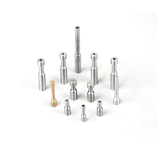
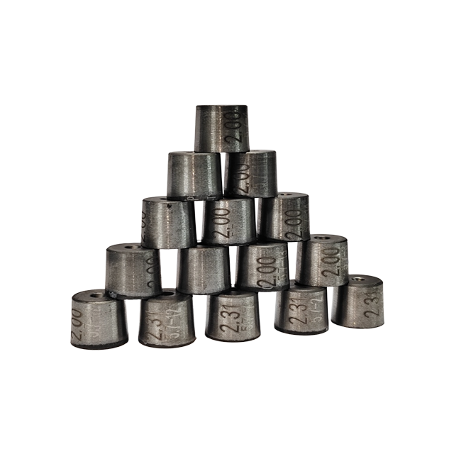
Polycrystalline Diamond (PCD) Drawing Dies are high-performance wire forming tools engineered to redefine efficiency in wire drawing processes. Crafted through advanced HPHT (High Pressure High Temperature) synthesis technology, these dies overcome the limitations of natural diamonds, delivering consistent performance across a wide range of wire materials and diameters. As a cornerstone in modern manufacturing, PCD Drawing Dies blend exceptional hardness, wear resistance, and structural stability, making them the preferred choice for industries demanding precision and long-lasting productivity. Whether processing fine wires for electronics or heavy-duty wires for industrial applications, these dies ensure smooth drawing operations with minimal downtime and superior wire quality.

In the rapidly growing solar energy sector, PV cutting wires require ultra-fine diameters and consistent tensile strength to ensure precise silicon wafer slicing. PCD Drawing Dies excel in this scenario by enabling continuous drawing of wires over extended lengths without compromising dimensional accuracy. The dies’ resistance to abrasion prevents wire surface defects, ensuring the cutting wires maintain sharpness and efficiency, which directly impacts the quality and yield of solar panels. Manufacturers benefit from reduced tool replacement frequency, aligning with the high-volume production needs of the photovoltaic industry.
Stainless steel wires are widely used in construction, automotive, and medical devices, where corrosion resistance and structural integrity are non-negotiable. Stainless steel wire drawing poses unique challenges due to the material’s hardness and tendency to cause tool wear. PCD Drawing Dies address this by offering exceptional durability, even when processing high-strength stainless steel alloys. The dies’ smooth working surface reduces friction between the wire and the die, minimizing heat generation and preventing wire deformation. This results in wires with uniform diameters, clean surfaces, and reliable mechanical properties, meeting the stringent standards of critical applications.
High-speed welding operations demand wires that feed smoothly and melt consistently, which relies heavily on the precision of the drawing process. High-speed welding wire lines operating at rapid feed rates require dies that can withstand intense pressure and friction. PCD Drawing Dies are designed to handle these high-speed conditions, ensuring stable wire feeding and consistent diameter control. The dies’ long service life reduces interruptions for tool changes, allowing welding wire manufacturers to meet tight production schedules while maintaining the quality required for strong, reliable welds.
Mold Type | Optimal Wire Range | Lifespan Index | Cost Performance | Typical Applications |
Natural Diamond Dies | Φ0.010-1.2mm | ★★★★ | ★★★ | Medical guidewires / Gold bonding wires |
PCD Dies | Φ0.03-20mm | ★★★★ | ★★★★ | Stainless steel wires / PV cutting wires |
Carbide Dies | Φ0.1-40mm | ★★ | ★★★★★ | Construction steel strands / Galvanized wires |
Nano-Coated Dies | Φ0.5-10mm | ★★★★★ | ★★★★★ | Superalloys / Copper-clad steel wires |
Single Crystal Dies | Φ0.015-1.0mm | ★★★★ | ★★★ | Semiconductor dicing / IC packaging |
PCD Drawing Dies feature a composite design combining a PCD diamond layer with a carbide substrate, a breakthrough that enhances both performance and safety. The diamond layer, synthesized from high-purity diamond powder, provides extreme hardness and wear resistance, while the carbide substrate adds structural rigidity and impact resistance. This combination significantly reduces the risk of die burst, even under high-pressure drawing conditions, ensuring operational safety and extending the die’s service life. The seamless integration of these two materials creates a tool that balances toughness and precision, outperforming single-material alternatives.
Every PCD Drawing Die undergoes meticulous design and machining to ensure optimal wire flow during the drawing process. The die’s inlet and outlet angles are precision-tuned to minimize friction and stress on the wire, reducing the likelihood of breakage and surface damage. The working area is polished to a mirror finish, which not only enhances wire surface quality but also reduces material buildup, further extending the die’s operational life. This attention to detail in design ensures that each wire drawn through the die meets exact dimensional specifications, making PCD Drawing Dies ideal for applications where precision is non-negotiable.
The core of each die is the PCD material, synthesized using state-of-the-art HPHT technology. This process creates a polycrystalline structure that offers superior hardness and wear resistance compared to natural diamonds. Unlike natural diamonds, which are limited by size and availability, synthetic PCD can be engineered to meet specific performance requirements, ensuring consistent quality across every die. The material’s resistance to thermal and chemical degradation makes it suitable for drawing a wide range of materials, including stainless steel, copper, aluminum, and various alloys, providing versatility for diverse manufacturing needs.
We understand that every wire drawing application is unique, which is why we offer comprehensive custom PCD Drawing Dies services tailored to your specific requirements. Our team of engineering experts works closely with you to design dies that align with your wire material, diameter, drawing speed, and production volume. Whether you need a die for ultra-fine wires as small as a few micrometers or larger industrial wires, we can adjust the die’s dimensions, working angles, and material composition to optimize performance. We also provide custom surface treatments and modifications to address specific challenges, such as reducing friction for high-speed applications or enhancing wear resistance for abrasive materials. With our customization services, you get a tool that is perfectly suited to your production process, maximizing efficiency and minimizing costs.
PCD Drawing Dies are highly versatile and compatible with a wide range of wire materials, including stainless steel, copper, aluminum, brass, titanium, and various high-temperature alloys. Their exceptional hardness and wear resistance make them particularly effective for processing hard or abrasive materials that would quickly wear down conventional dies.
While natural diamond dies offer excellent precision for fine wires, PCD Drawing Dies provide superior durability and cost-effectiveness for most industrial applications. They can handle larger wire diameters and higher drawing speeds, and their composite structure reduces the risk of breakage. Additionally, PCD dies are more readily available in custom sizes, making them a more flexible choice for diverse production needs.
Yes, our PCD Drawing Dies are designed to be refurbished, extending their service life and reducing overall costs. When the diamond layer shows signs of wear, our professional team can regrind and repolish the working surface to restore its precision and performance. Refurbishment is a cost-effective alternative to replacing the entire die, especially for high-value custom designs.
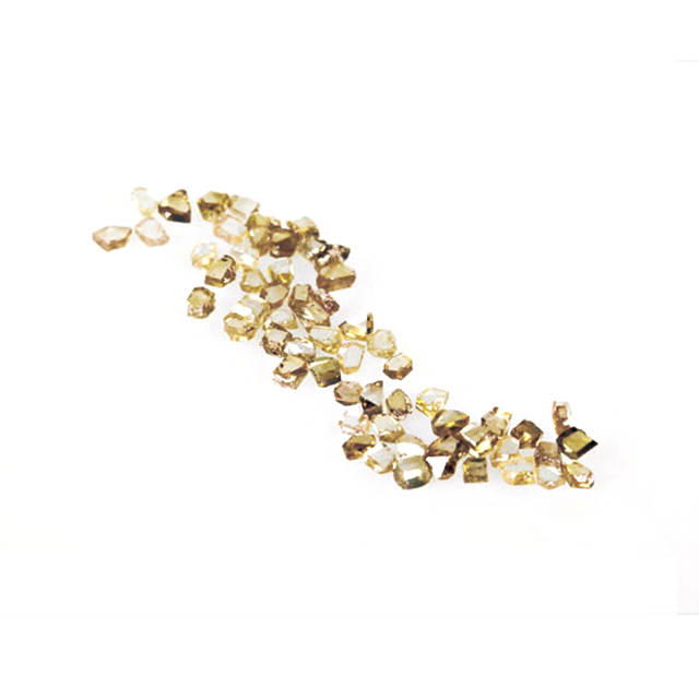
Polycrystalline Diamond (PCD) Drawing Dies are designed for precision and continuous wire drawing applications where dimensional consistency, wear resistance and stable wire surface quality are critical.
Available in multiple PCD core sizes and die configurations, these dies can be customized according to wire material, incoming diameter, finished diameter, drawing reduction and production conditions.
Key Features
PCD core for precision and continuous wire drawing
Nominal wire diameter range from 0.013 to 16 mm
Multiple PCD core sizes from D-6 to D-36
Thermal stability options of 650°C, 700°C and 1000°C depending on model
Custom bore diameter, reduction angle and bearing length
Suitable for soft and hard metallic wires
Suitable for single-pass and multi-pass wire drawing
Customized according to wire material and drawing conditions
During the wire drawing process, metal wire is pulled through a precision die to progressively reduce its cross-sectional area and achieve the required final diameter.
The internal geometry of the drawing die directly affects drawing force, dimensional accuracy, wire surface condition and production stability.
PCD drawing dies are available for both soft and hard wire materials, including copper, aluminum, brass, stainless steel, nickel, molybdenum, tungsten and other metallic wires.
The die design can be adapted according to the wire material, required reduction, drawing speed, lubrication conditions and required finished-wire accuracy.
Different PCD core sizes are available for different bore diameters and drawing conditions.
The appropriate model should be selected according to the required bore size, reduction angle, bearing length, wire material and production conditions.
PROD No. | MFG. No. | Thermal Stability in Air | Core Diameter d (mm) | Core Thickness t (mm) |
|---|---|---|---|---|
D-6 | WD705 | 700°C | 2.5 | 1.0 |
D-6 | WD805 | 1000°C | 2.5 | 1.0 |
D-12 | WD710 | 700°C | 3.2 | 1.5 |
D-12 | WD810 | 1000°C | 3.2 | 1.5 |
D-12 | WD910 | 700°C | 1.5 | 1.5 |
D-15 | WD715 | 700°C | 5.2 | 2.5 |
D-15 | WD815 | 1000°C | 5.2 | 2.5 |
D-15 | WD915 | 700°C | 4.0 | 2.3 |
D-18 | WD720 | 700°C | 5.2 | 3.5 |
D-18 | WD820 | 1000°C | 5.2 | 3.5 |
D-18 | WD920 | 700°C | 4.0 | 2.9 |
D-21 | WD925 | 700°C | 7.0 | 4.0 |
D-24 | WD930 | 700°C | 7.0 | 5.3 |
D-27 | WD940 | 700°C | 8.7 | 7.5 |
D-27 | WD945 | 700°C | 13.0 | 9.0 |
D-30 | WD950 | 700°C | 13.0 | 12.0 |
D-30 | WD360 | 650°C | 15.0 | 12.0 |
D-33 | WD360 | 650°C | 15.0 | 15.0 |
D-36 | WD470 | 650°C | 20.0 | 18.0 |
D-36 | WD480 | 650°C | 28.0 | 20.0 |
Nominal wire diameter range: 0.013–16 mm.
Final PCD die selection should consider the PCD core model together with the bore diameter, wire material, reduction angle and bearing configuration.
PCD drawing dies can be supplied in different bore sizes according to the incoming wire diameter, finished diameter and drawing sequence.
Customization can include:
Bore diameter
PCD core model
Reduction angle
Bearing length
Die outside diameter
Die height
Entrance and exit geometry
Multi-pass die sets
PCD drawing dies can be configured for different soft and hard metallic wire materials.
PCD drawing dies can be used for stainless steel wire drawing where stable bore geometry, dimensional consistency and wire surface condition are important.
The reduction angle and bearing length should be matched to the stainless steel material, incoming diameter, reduction per pass and drawing conditions.
Typical applications include:
Fine stainless steel wire
Precision stainless steel wire
Industrial stainless steel wire
Multi-pass stainless steel wire drawing
The following production footage shows a PCD drawing die used in an actual stainless steel wire drawing process.
It provides a practical view of continuous wire reduction under real production conditions.
This is a descriptive copy, which can be used to introduce the company or to highlight the features of a product. Whether you are looking to provide a comprehensive overview of your company's history, mission, and values, or to showcase the unique attributes and benefits of your product. It can help you connect with your audience, convey your brand's message effectively, and emphasize what sets your offerings apart from the competition.
PCD drawing dies can be used for continuous drawing of copper and copper alloy wires.
Typical applications include:
Copper wire
Brass wire
Copper alloy wire
Copper-clad wire
Electrical conductor wire
The die geometry can be adapted according to material ductility, drawing reduction and lubrication conditions.
Aluminum and aluminum alloy wires require stable material flow and appropriate lubrication during drawing.
The entrance, reduction and bearing geometry can be adjusted according to wire diameter and reduction ratio to improve drawing stability.
PCD drawing dies can also be configured for harder wire materials including:
Nickel wire
Molybdenum wire
Tungsten wire
Iron wire
Alloy steel wire
Copper-clad steel wire
Different materials require different die geometries because their deformation behavior, hardness and drawing requirements vary.
Precision fine-wire applications require stable bore geometry and consistent final wire dimensions.
PCD drawing dies can be selected for applications where dimensional consistency and long-term die stability are important during continuous production.
For welding wire production, stable wire diameter helps support consistent downstream feeding and processing.
PCD drawing dies can be configured for multi-pass welding wire production according to wire material and required finished diameter.
A PCD drawing die is not simply a hole with a fixed diameter.
Its internal profile contains several functional zones that guide, lubricate, reduce, size and release the wire during drawing.
Entrance / Lubrication Zone → Reduction Zone → Bearing Zone → Exit Zone
The entrance section guides the wire into the die and helps align it with the die centerline.
The lubrication section helps carry lubricant toward the deformation zone.
Its main functions include:
Guiding the wire into the die
Improving entry stability
Helping lubricant enter the die
Reducing initial friction
Supporting stable wire drawing
The reduction zone is the main deformation area of the drawing die.
The wire diameter is progressively reduced as the wire passes through this section.
The reduction angle influences:
Drawing force
Metal flow
Friction
Heat generation
Wire surface condition
Die wear
Drawing stability
An excessively large or small reduction angle can both negatively affect the drawing process, so the angle should be matched to the wire material and reduction ratio.
The bearing zone controls and stabilizes the final wire diameter.
Its geometry influences:
Final diameter
Diameter tolerance
Roundness
Surface quality
Friction
Die wear
A bearing that is too long can increase friction and temperature, while insufficient bearing length may reduce dimensional stability.
The exit zone allows the finished wire to leave the drawing die smoothly.
Correct exit geometry helps reduce:
Wire scratching
Wire vibration
Contact with the die outlet edge
Mechanical damage to the die outlet
Reduction angle and bearing length are two of the most important geometric parameters in a wire drawing die.
Design Parameter | Main Function | Possible Effect if Improperly Selected |
Reduction Angle | Controls wire deformation | Increased drawing force, heat or unstable deformation |
Reduction Zone Length | Controls deformation path | Uneven deformation and accelerated die wear |
Bearing Length | Stabilizes final wire diameter | Excess friction or insufficient dimensional control |
Bore Diameter | Determines finished size | Finished wire outside required dimension |
Surface Finish | Controls wire-to-die contact | Increased friction or surface damage |
Exit Geometry | Supports stable wire exit | Wire vibration or outlet damage |
The final geometry should therefore be determined according to the complete wire drawing conditions rather than the finished diameter alone.
Different wire materials require different deformation conditions.
The following values are engineering reference data for selecting the reduction angle according to wire elongation, shrinkage and material type.
Recommended Reduction Angle [α], Tolerance ±2°
Elongation (%) | Shrinkage (%) | Al / Ag / Gold / Zn | Cu / Al Alloy / Gold | Hard Al / Chromel Alloy | Copper Alloy / Brass / Stainless Steel | Alloy Steel / Mo / SS / Various Alloys | Copper Alloy / Brass / MIG Wire / Iron Dry Drawing | Alloy Steel / Dry Drawing | Hot Tungsten Filament |
5–9 | 5–8 | 14° | 12° | 10° | 9° | 8° | 7° | 6° | 10° |
9–14 | 8–12 | 16° | 14° | 12° | 11° | 10° | 9° | 8° | 10° |
14–19 | 12–16 | 18° | 18° | 14° | 13° | 12° | 11° | 10° | 12° |
19–33 | 16–25 | 21° | 21° | 18° | 16° | 15° | 14° | 12° | 12° |
33–54 | 25–35 | 24° | 24° | 20° | 19° | 18° | 17° | 15° | 14° |
Note: Actual reduction angles should be adjusted according to wire material, drawing speed, reduction per pass, lubrication and production requirements.
Selecting a PCD drawing die requires more than choosing the required finished wire diameter.
Different metals have different deformation characteristics.
Copper, aluminum, stainless steel, nickel and alloy wires may therefore require different reduction angles and bearing configurations.
Both the incoming wire diameter and required finished diameter should be provided.
For multi-pass drawing, the diameter sequence for each drawing pass is also useful.
The amount of area reduction in each drawing pass influences drawing force, deformation and die geometry.
Machine configuration, number of passes and speed relationships between drawing stages should be considered when selecting a complete die set.
Drawing speed affects friction and thermal conditions and should therefore be considered together with lubrication and die geometry.
Wet drawing, dry drawing and different lubricant systems can require different die profiles.
For precision wire production, provide:
Diameter tolerance
Roundness requirement
Surface quality requirement
These parameters help determine the required bearing and finishing conditions.
The maximum recommended bore size is influenced by the PCD core model, reduction angle and bearing percentage.
The following table provides engineering reference values for different PCD models.
Unit: mm
PROD No. | MFG. No. | BRG 0.1 / 8° | 12° | 16° | 20° | 24° | BRG 0.3 / 8° | 12° | 16° | 20° | 24° | BRG 0.5 / 8° | 12° | 16° | 20° | 24° |
D-6 | WD705 / WD805 | 0.45 | 0.62 | 0.76 | 0.88 | 0.99 | 0.41 | 0.54 | 0.65 | 0.74 | 0.81 | 0.37 | 0.48 | 0.57 | 0.63 | 0.68 |
D-12 | WD710 / WD810 | 0.71 | 0.97 | 1.19 | 1.39 | 1.55 | 0.64 | 0.85 | 1.02 | 1.15 | 1.27 | 0.59 | 0.76 | 0.89 | 0.99 | 1.07 |
D-12 | WD910 | 0.66 | 0.90 | 0.96 | 0.96 | 0.96 | 0.60 | 0.79 | 0.94 | 0.96 | 0.96 | 0.55 | 0.71 | 0.82 | 0.92 | 0.96 |
D-15 | WD715 / WD815 | 1.23 | 1.68 | 2.06 | 2.40 | 2.68 | 1.11 | 1.47 | 1.76 | 1.99 | 2.19 | 1.01 | 1.31 | 1.53 | 1.71 | 1.85 |
D-15 | WD915 | 1.07 | 1.47 | 1.80 | 2.09 | 2.34 | 0.97 | 1.29 | 1.54 | 1.74 | 1.91 | 0.89 | 1.14 | 1.34 | 1.49 | 1.62 |
D-18 | WD720 / WD820 | 1.74 | 2.39 | 2.94 | 3.40 | 3.73 | 1.58 | 2.10 | 2.50 | 2.83 | 3.11 | 1.44 | 1.86 | 2.18 | 2.43 | 2.62 |
D-18 | WD920 | 1.38 | 1.89 | 2.33 | 2.60 | 2.60 | 1.25 | 1.66 | 1.98 | 2.25 | 2.46 | 1.14 | 1.48 | 1.73 | 1.93 | 2.08 |
D-21 | WD925 | 1.95 | 2.68 | 3.28 | 3.81 | 4.26 | 1.77 | 2.34 | 2.79 | 3.17 | 3.47 | 1.62 | 2.08 | 2.44 | 2.71 | 2.94 |
D-24 | WD930 | 2.62 | 3.59 | 4.41 | 5.08 | 5.08 | 2.38 | 3.15 | 3.76 | 4.26 | 4.67 | 2.17 | 2.80 | 3.28 | 3.65 | 3.95 |
D-27 | WD940 | 3.75 | 5.15 | 6.32 | 6.42 | 6.42 | 3.41 | 4.51 | 5.39 | 6.10 | 6.42 | 3.12 | 4.01 | 4.69 | 5.23 | 5.66 |
D-27 | WD945 | 4.58 | 6.28 | 7.72 | 8.94 | 9.42 | 4.15 | 5.51 | 6.57 | 7.45 | 8.17 | 3.80 | 4.90 | 5.73 | 6.38 | 6.91 |
D-30 | WD950 | 6.13 | 8.40 | 9.42 | 9.42 | 9.42 | 5.56 | 7.36 | 8.80 | 9.42 | 9.42 | 5.09 | 6.55 | 7.66 | 8.53 | 9.24 |
D-30 | WD360 | 6.13 | 8.40 | 10.32 | 10.92 | 10.92 | 5.56 | 7.36 | 8.80 | 9.96 | 10.92 | 5.09 | 6.55 | 7.66 | 8.53 | 9.24 |
D-33 | WD360 | 6.13 | 8.40 | 10.32 | 10.92 | 10.92 | 5.56 | 7.36 | 8.80 | 9.96 | 10.92 | 5.09 | 6.55 | 7.66 | 8.53 | 9.24 |
D-36 | WD470 | 9.23 | 12.65 | 14.89 | 14.89 | 14.89 | 8.37 | 11.08 | 13.24 | 14.89 | 14.89 | 7.64 | 9.86 | 11.53 | 12.84 | 13.90 |
D-36 | WD480 | 10.26 | 14.07 | 17.27 | 20.03 | 20.88 | 9.30 | 12.32 | 14.71 | 16.68 | 18.31 | 8.51 | 10.96 | 12.82 | 14.29 | 15.46 |
Selection Note
The figures above are engineering reference values for the PCD core itself. Final product selection should still be based on the required wire diameter and actual drawing process.
The working cone and bearing area are critical wire-contact surfaces and require precision finishing.
A properly finished internal surface can help:
Reduce wire-to-die friction
Improve wire surface condition
Improve dimensional stability
Reduce unnecessary wear
Support stable continuous drawing
Different wire materials and production lines do not necessarily require the same internal die geometry.
PCD drawing dies can therefore be customized according to:
Wire material
Incoming diameter
Finished diameter
Reduction per pass
Drawing speed
Lubrication
Required tolerance
Drawing machine
Existing die dimensions
Available customization includes:
Bore Diameter · Reduction Angle · Bearing Length · PCD Core Model · Die OD · Die Height · Entrance Geometry · Exit Geometry · Multi-Pass Die Sets
Multi-pass drawing requires the complete drawing sequence to be considered rather than treating every die as an independent component.
Die selection may involve:
Incoming wire diameter
Final wire diameter
Number of drawing passes
Diameter at each pass
Drawing machine speed ratio
Reduction distribution
Lubrication conditions
For multi-pass applications, customers are encouraged to provide the complete drawing sequence so that the die sizes can be evaluated as a system.
Please provide:
Wire material
Incoming wire diameter
Finished wire diameter
Number of passes
Diameter of each pass, if available
Drawing machine type
Drawing speed
Wet or dry drawing
Lubricant type, if available
Required tolerance
Required surface quality
Existing die OD and height
This video introduces the basic principle of die matching for multi-pass wire drawing. Proper die size and reduction distribution help support stable and continuous wire drawing production.
Die Material | Main Characteristics | Typical Applications |
PCD | High wear resistance and stable geometry | Fine, precision and continuous wire production |
Natural Diamond | Suitable for very fine precision wire | Ultra-fine wire drawing |
Tungsten Carbide | Good impact resistance and economical | Coarse and medium wire drawing |
Coated Drawing Dies | Specialized surface performance | Selected abrasive or special wire applications |
The appropriate die material should be selected according to wire type, diameter, drawing speed, production volume and required accuracy.
A PCD drawing die is a wire drawing tool using a polycrystalline diamond core. The wire passes through the precision die profile and is progressively reduced to the required diameter.
PCD drawing dies can be configured for copper, aluminum, brass, stainless steel, nickel, molybdenum, tungsten, iron and various alloy wires.
The supplied product data gives a nominal wire diameter range of 0.013–16 mm.
Actual die selection should also consider the PCD core model and internal geometry.
Selection should consider:
Wire material
Incoming diameter
Finished diameter
Reduction per pass
Reduction angle
Bearing length
Drawing speed
Lubrication
Required tolerance
The reduction angle determines how the wire deforms as it passes through the die.
An unsuitable angle can affect drawing force, friction, heat generation, wire surface quality and drawing stability.
The bearing section controls and stabilizes the final wire diameter.
A bearing that is too long can increase friction, while one that is too short may reduce dimensional stability.
Yes. Bore diameter, reduction angle, bearing length, die dimensions and multi-pass die sets can be customized according to the wire drawing process.
Customers can provide the incoming diameter, finished diameter, drawing machine and drawing sequence so that the complete die configuration can be evaluated.
Magnet Wire is a specialized insulated conductor used in motors, transformers, generators, and other electromagnetic devices. Its performance depends on every manufacturing stage, including wire drawing, annealing, enameling, curing, and quality inspection. Precision wire drawing dies are essential for achieving accurate wire dimensions, smooth surface finishes, and reliable insulation adhesion. This guide explains the complete magnet wire manufacturing process, compares copper and aluminum conductors, and outlines key supplier evaluation criteria to help manufacturers improve product quality, electrical performance, and long-term reliability.
The Wire Drawing Process is a critical manufacturing method for producing precision wire with excellent dimensional accuracy, surface quality, and mechanical properties. From material preparation and descaling to lubrication, wire drawing dies, annealing, and final quality inspection, every production stage directly affects wire performance and manufacturing efficiency. This guide explains each step of the wire drawing process and provides practical recommendations for reducing wire defects, improving production yield, extending die life, and achieving consistent product quality across various industrial applications.
Diamond vs. Tungsten Carbide Wire Drawing Dies is a critical comparison for manufacturers seeking higher production efficiency, better wire quality, and longer tooling life. Each die material offers unique advantages in wear resistance, impact strength, surface finish, and operating cost. This guide explains the differences between tungsten carbide, PCD, natural diamond, and CVD diamond dies, helping manufacturers choose the most suitable wire drawing die based on wire material, production volume, precision requirements, and long-term manufacturing performance.