Views: 0 Author: Site Editor Publish Time: 2026-07-21 Origin: Site


High-performance electrical applications rely entirely on the integrity of their electromagnetic coils. From electric vehicle motors and industrial generators to utility-scale transformers, the conductor winding forms the heart of the system. A single microscopic flaw in the conductor can lead to catastrophic short circuits and complete system failure. Procurement and engineering teams often struggle to evaluate magnet wire quality beyond basic specification sheets. Inconsistent wire diameter, poor surface finish, and microscopic burrs lead to insulation breakdown. These defects reduce the lifespan and efficiency of the end product.
Understanding the end-to-end manufacturing process provides a reliable indicator of final product quality. Specifically, assessing how a supplier utilizes and maintains tooling reveals the true capability of their production floor. The condition of the manufacturing equipment directly determines the magnet wire's dimensional accuracy, enamel adhesion, and overall electrical reliability. By examining these practices, engineers can mitigate risks before the wire ever reaches the winding machines.
Fundamental Function: Magnet wire (enameled wire) is an insulated copper or aluminum conductor designed to interchange electrical and magnetic energy when wound into a coil and energized to create an electromagnetic field.
Manufacturing Critical Path: The production sequence—drawing, annealing, enameling, and spooling—dictates mechanical and electrical performance.
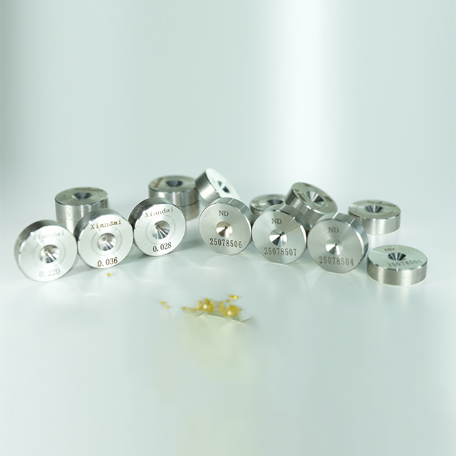
The Role of Tooling: Precision wire drawing dies are the most critical variable in the manufacturing process, directly controlling the surface finish required for defect-free insulation and the dimensional tolerances required for optimal coil fill factors.
Evaluation Criteria: Selecting a magnet wire supplier requires auditing their tooling maintenance protocols, in-line flaw detection capabilities, and adherence to NEMA/IEC standards.
Table of Contents
Magnet wire, frequently referred to as enameled wire, operates as a highly specialized electrical conductor. Wrapping these insulated conductors into a tight coil and passing an electrical current through them generates a controlled electromagnetic field. This fundamental principle of electromagnetism drives nearly all modern rotational machinery and power transformation equipment. Traditional thick polymer insulation, like the PVC used in residential wiring, fails in these applications. Thick insulation creates excessive bulk. Engineers require ultra-thin coatings to maximize winding density. A higher winding density allows more conductive material to fit within a confined space, directly increasing the magnetic force and efficiency of the component.
Different applications demand specific performance characteristics from the magnet wire. The operational environment dictates the required mechanical, thermal, and electrical properties. We see these variations across several core sectors.
Motors and Generators: These components endure high-rotational stresses and intense vibration. The magnet wire requires exceptional mechanical adhesion of the enamel to prevent flaking during operation.
Transformers and Inductors: These static devices manage high-voltage potentials and significant thermal dissipation. The insulation must withstand continuous high temperatures without degrading.
Solenoids and Instruments: These applications involve high-speed automated winding. Tensile strength and low friction coefficients are paramount to prevent wire breakage during manufacturing.
Audio Speakers and Voice Coils: Specialized micro-wire demands flawless geometric consistency to ensure accurate sound reproduction and prevent distortion.
Engineers must evaluate the trade-offs between conductivity, weight, and tensile strength when selecting the core conductor material. Copper and aluminum dominate the market, each serving distinct engineering needs based on physical properties.
Property | Copper Magnet Wire | Aluminum Magnet Wire |
|---|---|---|
Electrical Conductivity | Excellent (Standard reference) | Approximately 61% of Copper |
Weight and Density | Heavy (8.96 g/cm³) | Lightweight (2.70 g/cm³) |
Tensile Strength | High (Resists stretching) | Lower (Requires careful winding) |
Primary Applications | High-efficiency motors, micro-electronics | Aerospace, large transformers, automotive |
Performance ratios dictate the choice in specific applications. Aerospace engineers prioritize weight reduction, making aluminum the superior choice despite its lower conductivity. Conversely, designers of compact, high-efficiency consumer appliances rely on copper to achieve the necessary magnetic field strength within a restricted physical footprint.
Magnet wire utilizes ultra-thin polymer films instead of thick extruded plastics. These films include polyurethane, polyamide-imide, and polyesterimide. The liquid enamel is applied and cured in microscopic layers. This thin-film approach achieves the necessary dielectric strength while consuming minimal space. Thermal class ratings define the maximum continuous operating temperature the insulation can withstand. Ratings typically range from 105°C to 240°C and beyond. Selecting the correct thermal class prevents premature insulation breakdown under heavy electrical loads.
Transforming raw metal into precision magnet wire requires a tightly controlled manufacturing sequence. Each step builds upon the success of the previous operation. Any deviation in the early stages amplifies into critical defects in the final product.
The process begins with continuous cast copper or aluminum rod, typically 8mm in diameter. Heavy machinery pulls this rod through a series of large reduction dies. This initial breakdown transitions the bulk material into intermediate wire sizes. The metal undergoes severe plastic deformation during this stage. Engineers must manage work hardening. As the metal compresses and stretches, its crystalline structure becomes rigid and brittle. Careful control of reduction ratios prevents the wire from fracturing under the immense drawing tension.
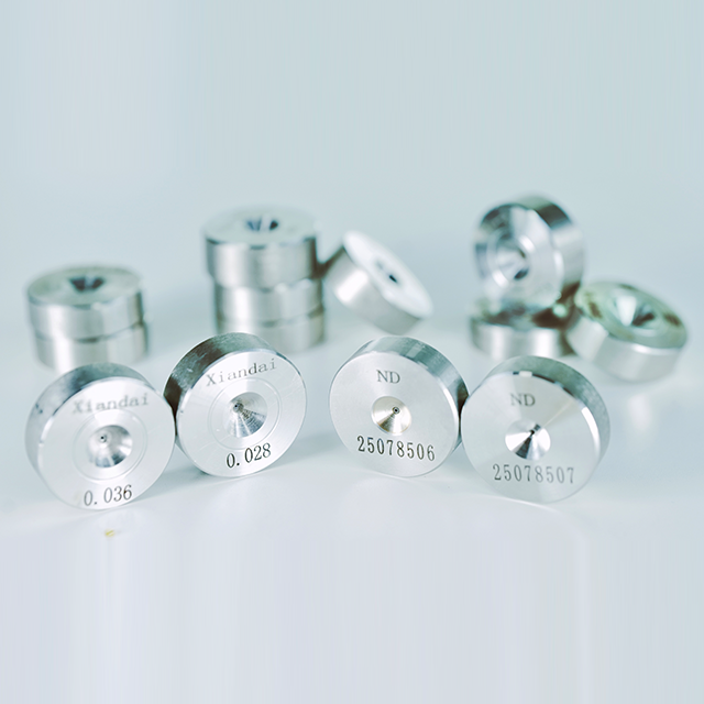
Following the initial breakdown, the intermediate wire enters the precision sizing phase. A series of progressively smaller Wire Drawing Dies reduces the wire to its exact final diameter. The physics of the drawing process rely on precise internal die geometry. The reduction angle guides the wire into the bearing area, which determines the final diameter and surface finish. Slip and non-slip machine dynamics control the tension between each die station. Friction management remains absolute. The chemistry of drawing lubricants minimizes thermal stress, prevents metal-to-metal welding, and extends the operational life of the tooling.
The aggressive reduction in the drawing phase leaves the wire highly stressed and brittle. It cannot be wound into coils in this state. In-line continuous annealing restores the necessary ductility. The wire passes through an electrically heated chamber or over electrified sheaves, raising its temperature to recrystallize the metal grain structure. Preventing oxidation is critical during this high-temperature phase. The annealing process occurs within a controlled atmosphere, typically utilizing steam or nitrogen, to keep the bare wire surface perfectly clean and receptive to the enamel coating.
The bare, annealed wire immediately enters the enameling section. Liquid enamel is applied through a multi-pass system. Applicator dies or specialized felt wipe away excess liquid, leaving a precise, concentric layer of polymer. The wire then travels through vertical or horizontal thermal curing ovens. The intense heat drives off the solvents and forces the cross-linking of the polymer chains. This process is repeated multiple times. Building the insulation through many thin layers ensures a stronger, more flexible, and defect-free coating compared to a single thick application.
After the final enamel layer cures, the wire receives a specialized surface treatment. Applicators deposit microscopic layers of wax or specialized oil onto the finished insulation. This lubrication facilitates high-speed coil winding at the customer's facility. It lowers the friction coefficient, allowing the wire to slide into tight stator slots without scraping or damaging the thin insulation. Finally, precision tension controls guide the wire onto delivery spools, ensuring an even lay that prevents tangling during subsequent unwinding.
The integrity of the insulation relies entirely on the condition of the bare wire beneath it. The tooling used to shape that bare wire acts as the most significant variable in the entire production cycle. Flawed tooling guarantees a flawed final product.
Microscopic scoring from worn tooling creates surface peaks and valleys on the bare conductor. Because the enamel layer is exceptionally thin, these copper or aluminum peaks can protrude entirely through the liquid coating before it cures. Even if the peaks do not breach the surface, they create areas of dangerously thin insulation. There is a direct correlation between die polish quality and high-voltage breakdown resistance. A mirror-like surface finish ensures uniform enamel distribution, maximizing the dielectric strength and preventing short circuits.
Tool wear directly impacts wire diameter consistency. As the bearing area of the die erodes, the wire becomes progressively larger. Oversized wire creates severe problems during coil winding. It reduces the number of turns that can fit into a motor stator slot or transformer bobbin. This degrades the magnetic performance and efficiency of the device. Strict dimensional tolerance ensures the calculated fill factor remains accurate, allowing engineers to design compact, high-power electromagnetic components.
Manufacturers select die materials based on the specific stage of the drawing process and the required final wire characteristics. Each material offers distinct advantages for specific production phases.
Die Material | Primary Application Stage | Key Characteristics |
|---|---|---|
Polycrystalline Diamond (PCD) | Intermediate drawing | High durability, long tool life, resists catastrophic failure under heavy loads. |
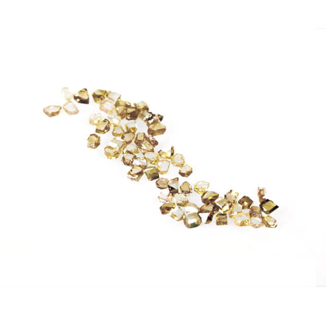
Natural/Synthetic Single Crystal Diamond | Final sizing of fine wire | Flawless crystalline structure, superior polish, mirror-like surface finish. |
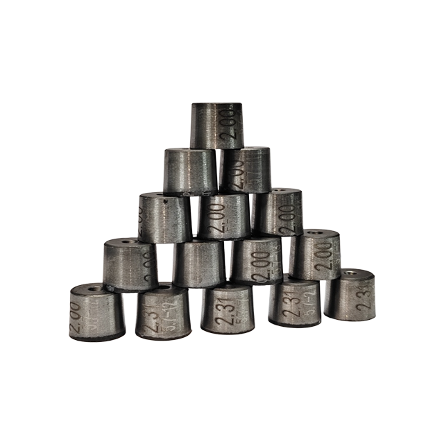
Tungsten Carbide | Initial heavy rod breakdown | High impact resistance, toughness, withstands violent reduction forces. |
Selecting a reliable supplier requires moving beyond basic data sheets. Engineers must audit the manufacturer's internal process controls to ensure consistent quality across long production runs.
Engineers must ask suppliers specific questions regarding their tooling maintenance programs. Inquire about their replacement schedules and internal re-cutting or polishing capabilities. A manufacturer that runs tooling until it fails will produce inconsistent wire. A proactive maintenance program, where dies are routinely inspected, resized, and repolished before they exceed tolerance limits, demonstrates a commitment to foundational quality control.
Modern manufacturing requires continuous monitoring. Verify the necessity of continuous laser diameter measurement immediately following the final drawing stage. This ensures the bare wire remains strictly within tolerance before enameling begins. Furthermore, high-voltage continuity testing, often called pin-hole detection, is mandatory during the enameling phase. This system applies a continuous voltage to the moving wire, instantly detecting and logging any microscopic breaches in the insulation.
Verify the supplier's adherence to international standards such as NEMA MW 1000, IEC 60317, and JIS C 3202. These standards dictate the baseline mechanical, electrical, and thermal performance requirements. Request statistical process control (SPC) data for critical parameters like wire diameter and dielectric breakdown voltage. Transparent SPC reporting proves the manufacturer maintains a stable, predictable process capable of meeting tight engineering tolerances.
Integrating magnet wire into a production line carries inherent risks. Identifying these risks early allows engineering teams to implement effective mitigation strategies during the procurement phase.
The most common cause of pinholes is copper dust accumulation in the drawing equipment or microscopic burrs created by improper internal die geometry. These defects puncture the thin enamel. To mitigate this risk, specify the maximum allowable faults per 100 feet or meters directly in the procurement contract. Require the supplier to provide continuous in-line fault detection logs for every spool delivered.
Inconsistent electrical resistance disrupts the performance of precision coils. The primary cause is diameter variation due to thermal expansion in the drawing machinery or gradual tool wear during long production runs. Mitigate this by requiring batch-specific resistance testing data. Ensure all resistance measurements are standardized to a specific temperature, typically 20°C, to account for environmental variables during testing.
If the wire is too stiff, it will not lay flat in the coil and will spring out of the stator slots. This is caused by incomplete annealing following aggressive reduction in the drawing stages. The metal retains internal stress. Implement strict elongation and springback testing during incoming quality inspection. Reject batches that do not meet the specified softness parameters to prevent costly downtime on automated winding machines.
Securing flawless magnet wire performance starts with uncompromised conductor preparation and precision tooling; XIANDAI is a trusted professional manufacturer specializing in premium diamond and tungsten carbide wire drawing dies, committed to helping global magnet wire producers achieve flawless surface integrity, tight tolerances, and superior insulation reliability.
Request technical data sheets and sample spools for extensive winding trials on your specific equipment.
Audit the supplier's tooling maintenance logs to verify proactive replacement of Wire Drawing Dies.
Establish maximum allowable fault limits in your procurement contracts based on continuous in-line pinhole detection data.
Require batch-specific resistance and elongation testing data standardized to 20°C for every shipment.
A: Regular electrical wire uses thick extruded plastics like PVC for insulation and is designed for power transmission. Magnet wire uses ultra-thin, multi-layered polymer enamel. This thin insulation allows the wire to be wound into tight coils to generate electromagnetic fields without taking up excessive space.
A: Tooling controls the exact physical diameter of the bare wire. If a worn tool allows the wire to become oversized, the cross-sectional area increases, lowering the resistance. If the wire is drawn too small, resistance increases. Precise tooling ensures consistent electrical conductivity across the entire spool.
A: Copper offers superior electrical conductivity and higher tensile strength compared to aluminum. This allows engineers to design smaller, more efficient motors and transformers. Aluminum is used when weight reduction is the primary design constraint, such as in aerospace applications.
A: The diameter is controlled by pulling the rod through a series of progressively smaller precision dies. The final die dictates the exact finished diameter of the bare conductor. Continuous in-line laser micrometers monitor the wire to ensure it remains within strict tolerances.
A: Pinholes are typically caused by surface defects on the bare wire, such as microscopic burrs, scratches, or embedded copper dust. These defects protrude through the ultra-thin liquid enamel before it cures, creating a breach in the insulation and a potential short circuit.
A: Replacement schedules depend on the material being drawn, the operating speed, and the die material. Manufacturers must continuously monitor wire diameter and surface finish, replacing or repolishing the tooling long before the wire approaches the maximum allowable tolerance limits.
A: Thermal class ratings indicate the maximum continuous operating temperature the insulation can withstand for a 20,000-hour lifespan. Standard ratings typically include 105°C, 130°C, 155°C, 180°C, 200°C, 220°C, and 240°C, depending on the specific polymer enamel used.