Views: 0 Author: Site Editor Publish Time: 2026-07-21 Origin: Site


Industrial wire production relies on strict dimensional control and surface integrity. The cold drawing process acts as a primary variable in manufacturing everything from aerospace fasteners to electrical conductors. Manufacturers frequently face a trade-off between maximizing drawing speed and minimizing wire breakage, surface defects, and premature tooling wear. Achieving consistent cross-sectional reduction without compromising mechanical properties requires precise control over every phase of production. This guide breaks down the exact wire drawing process steps. We detail how material preparation, lubrication, and the strategic selection of Wire Drawing Dies dictate final product quality and operational efficiency. You will learn how to optimize your production line, reduce scrap rates, and extend the lifespan of your tooling through proper implementation of these core manufacturing principles.
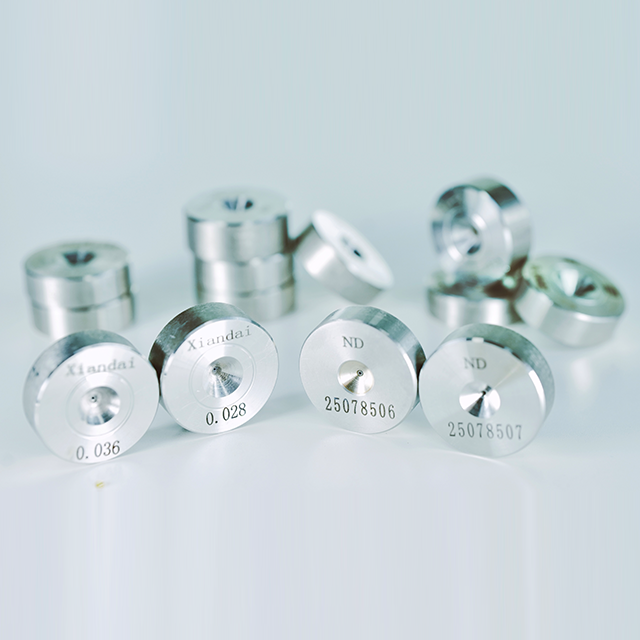
Preparation is Non-Negotiable: Effective chemical or mechanical descaling prevents mill scale from acting as an abrasive, which is the leading cause of premature die failure.
Die Geometry Dictates Yield: The approach angle, bearing length, and material of wire drawing dies must be precisely matched to the wire alloy and reduction requirements to prevent work hardening and breakage.
Lubrication Controls Thermal Dynamics: Selecting between dry and wet drawing lubricants is critical for managing friction and heat generation during high-speed, multi-draft continuous drawing.
Table of Contents
Establishing baseline metrics for yield strength, tensile strength, and required ductility post-draw ensures the final product meets strict engineering standards. Operators must set acceptable variance limits for cross-sectional area and surface finish quality before initiating any production run. Evaluating the impact of drawing speed on the degradation rate of Wire Drawing Dies helps minimize machine downtime and maintain continuous throughput. Understanding standard starting stock sizes, such as 8mm rod for copper, aluminum, or steel, provides a solid foundation for the entire operation. The incoming material grain structure directly affects the initial draft. This dictates the maximum allowable reduction ratio without causing internal fractures.
Process objectives vary significantly depending on the end application. Electrical conductors require maximum conductivity and flexibility. This necessitates specific reduction schedules that avoid excessive work hardening. Structural cables prioritize ultimate tensile strength, requiring aggressive cold working to align the grain structure. By defining these parameters early, production engineers select the appropriate machinery, lubrication systems, and die geometries to achieve the desired mechanical properties consistently. You must monitor these metrics throughout the shift to catch deviations before they result in rejected coils.
Application Type | Primary Objective | Key Quality Metric | Typical Material |
|---|---|---|---|
Electrical Conductors | Maximum Conductivity | Surface Finish & Flexibility | Copper, Aluminum |
Structural Cables | High Tensile Strength | Grain Alignment | High-Carbon Steel |
Aerospace Fasteners | Fatigue Resistance | Dimensional Accuracy | Titanium, Alloy Steel |
Medical Devices | Biocompatibility | Pristine Surface Integrity | Stainless Steel, Nitinol |
Drawing raw, hot-rolled rod without preparation leads to catastrophic tooling failure. Mill scale forms an oxide layer during the hot rolling process. This scale acts as a severe abrasive. If allowed to enter the reduction zone, this scale scores the die surface and embeds itself into the wire. This ruins the surface finish and compromises structural integrity. You must remove this scale completely before the wire touches the first die.
Mechanical methods physically fracture and remove the oxide layer. Reverse-bend descalers force the wire over a series of staggered pulleys. This causes the brittle scale to flake off while the ductile core bends. Shot blasting and aggressive brushing provide additional mechanical cleaning. These methods eliminate the need for hazardous chemical disposal. They reduce environmental compliance burdens on your facility. However, mechanical descaling carries a risk of incomplete scale removal. Microscopic surface pits can still introduce abrasives into the drawing process.
Pass the raw rod through a reverse-bend descaler to break the primary scale layer.
Route the wire through a shot blasting chamber to remove residual flakes.
Utilize aggressive wire brushing stations to clean microscopic pits.
Inspect the surface visually and with tactile sensors to ensure complete scale removal.
Chemical pickling utilizes aggressive acid baths to dissolve the scale completely. Facilities typically use hydrochloric or sulfuric acid. This method ensures a pristine surface, reaching into microscopic crevices that mechanical methods miss. Operators must carefully control the acid concentration, temperature, and immersion time. Pickling introduces environmental compliance challenges regarding acid disposal and fume extraction. Improper pickling of high-carbon steels leads to hydrogen embrittlement. Hydrogen atoms diffuse into the metal lattice, causing unpredictable brittle fractures during drawing.
Once the wire is clean, it requires a carrier coating to facilitate lubricant adhesion prior to the first draft. Bare metal struggles to retain dry drawing lubricants under extreme pressure. Applying borax, lime, or complex phosphate coatings creates a porous surface layer. This layer traps the lubricant, ensuring a continuous boundary layer between the wire and the die. Phosphate coatings react chemically with the steel surface. They provide exceptional lubricant retention for severe reductions.
Before the drawing process begins, operators physically reduce the rod end diameter to pass it through the first die block. This initial preparation is known as pointing. It requires specialized equipment depending on the wire gauge and material hardness. You cannot force a full-diameter rod through a reduction die without this step.
Rotary Swaging: This method utilizes rapid, repeated hammer blows from rotating dies to reduce the wire diameter uniformly. It delivers consistent results and maintains the material's structural integrity. We recommend this for high-volume industrial setups.
Roll Pointing: Utilizing grooved rollers to squeeze and elongate the wire end, roll pointing provides efficient reduction for heavy-gauge wire and rod breakdown machines. It operates faster than swaging for large diameters but produces a less uniform taper.
Manual Tapering: Flat filing the wire end to a taper or rotating the wire while hammering works well for prototyping and low-volume runs. While labor-intensive, it requires minimal equipment investment.
Once pointed, the operator threads the wire through the die and secures it to the drawing block, or capstan. Heavy-duty gripping jaws grab the pointed end. As the capstan rotates, it initiates the pulling tension. This draws the full-diameter wire through the reduction zone and establishes the continuous process. Proper threading ensures the wire enters the die at the correct angle, preventing uneven wear on the die entrance.
Friction reduction is paramount in cold drawing. Without adequate lubrication, the extreme pressures and temperatures generated during plastic deformation cause galling and scoring. The wire material will weld to the die surface. Effective lubrication systems manage thermal dynamics and protect your tooling investment. You must match the lubricant to the specific alloy and reduction schedule.
Dry drawing utilizes powdered soaps placed in a die box immediately preceding the die. Facilities typically use sodium or calcium-based stearates. As the coated wire passes through the box, it picks up the powder. The immense pressure within the die forces the powder to undergo a phase change. It acts as a highly viscous hydrodynamic film. This method suits heavy-gauge and intermediate carbon steel wire. High reduction ratios generate substantial heat, and dry powders withstand these temperatures better than liquids.
Wet drawing submerges the wire and dies entirely in liquid lubricants. Operators use straight oils or water-soluble emulsions. This method excels at heat dissipation. It is mandatory for fine wire, non-ferrous metals like copper and aluminum, and high-speed continuous drawing operations. The liquid continuously flushes away microscopic metallic fines. This maintains a pristine surface finish critical for electrical and medical applications.
Lubrication Type | Base Material | Primary Use Case | Cooling Capacity |
|---|---|---|---|
Dry Powder | Sodium Stearate | High-Carbon Steel, Heavy Gauge | Low to Moderate |
Dry Powder | Calcium Stearate | Stainless Steel, Aggressive Drafts | Moderate |
Wet Emulsion | Water-Soluble Oil | Copper, Aluminum, Fine Wire | Excellent |
Straight Oil | Mineral Oil | Specialty Alloys, Medical Wire | Good |
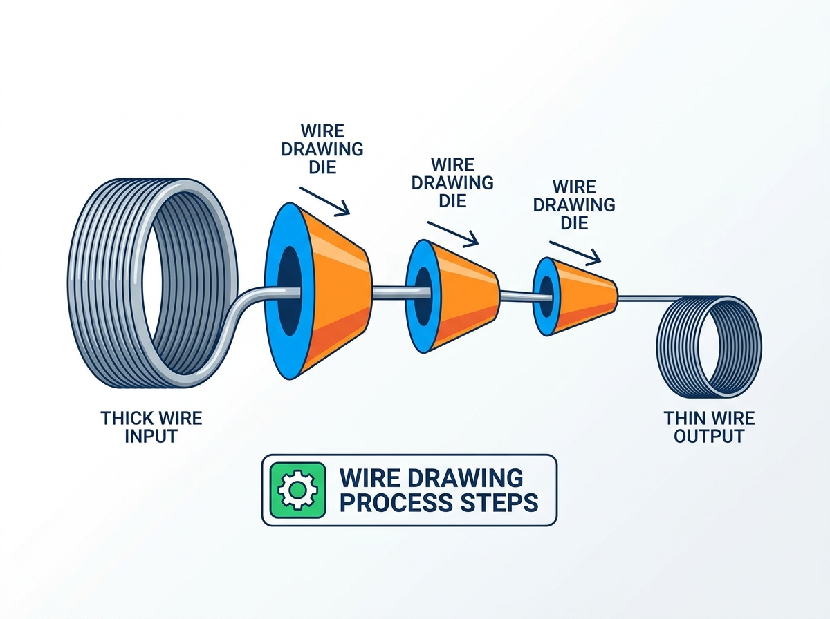
The core of the process relies on the mechanics of plastic deformation. Pulling force applied by the capstan and compressive force generated by the die geometry converge to reduce the wire's diameter. The volume of the material remains constant, but its cross-sectional area decreases while its length increases. You must control the tension precisely to prevent necking or breaking.
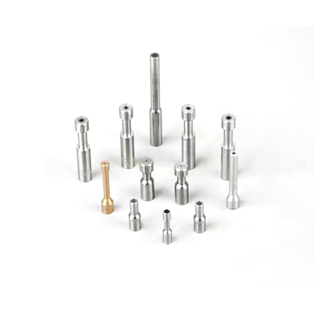
Bell (Entrance): The wide opening guides the wire and channels lubricant directly into the reduction zone. A properly angled bell ensures smooth lubricant flow.
Approach Angle (Reduction Cone): This is the critical zone where plastic deformation occurs. You must optimize these angles for the specific material to prevent center-burst defects. Harder materials generally require shallower angles.
Bearing (Cylindrical Section): This flat section dictates the final diameter, ensures roundness, and polishes the surface finish. The length of the bearing affects the final wire straightness.
Back Relief (Exit): A slight outward taper prevents the wire from scraping against the die edge as it exits and undergoes natural elastic springback.
Selecting the right material for your Wire Drawing Dies determines your production run length and surface quality. Tungsten Carbide offers high durability against impact and handles severe initial reductions well. It is cost-effective for ferrous metals and heavy rod breakdown. Polycrystalline Diamond provides superior lifespan and uniform wear. It maintains strict dimensional tolerances over long runs, making it ideal for continuous multi-draft drawing of non-ferrous metals. Natural Diamond provides pristine surface finishes and extreme hardness. Operators reserve it for ultra-fine wire and medical-grade applications where surface defects are unacceptable.
The drawing process occurs in stages. The rod breakdown stage passes standard 8mm wire rod through heavy-duty dies to achieve intermediate diameters. Intermediate drawing translates this bulk rod into functional engineering-grade wire. Fine and ultra-fine drawing utilizes high-precision machines with specialized dies to produce wire for delicate electrical applications. Continuous multi-draft machines route the wire through a series of progressively smaller dies. They utilize slip or non-slip capstans to manage the increasing wire speed as it elongates.
Cold drawing alters the crystalline structure of the metal. The grains elongate in the direction of the draw. This increases tensile strength but significantly reduces ductility. This phenomenon is known as work hardening. It eventually makes the wire too brittle for further reduction or end-use application. You must implement thermal treatments to restore the material's workability.
In-line continuous annealing uses electrical resistance or induction heating to restore ductility between drafts without halting production. The wire passes over electrified sheaves, heating rapidly to its recrystallization temperature before being quenched. This method integrates seamlessly into high-speed lines. Batch or bell annealing processes full coils in a controlled atmosphere furnace. The coils soak at high temperatures for hours. This allows complete grain recrystallization in an oxygen-free environment to prevent scaling.
Monitor the cumulative reduction ratio to determine the exact point where work hardening risks fracture.
Route the wire through the continuous annealing sheaves, ensuring consistent contact to prevent arcing.
Control the voltage and line speed to achieve the precise recrystallization temperature for the specific alloy.
Quench the wire immediately in a water bath to lock in the restored grain structure.
Dry the wire thoroughly before it enters the next drawing stage or spooling equipment.
The final stage requires precise handling to package the finished wire without introducing defects. Operators utilize dancer arms and accumulators to maintain consistent winding tension. Improper tension causes wire stretching, tangling, or uneven spooling. This disrupts the downstream customer's payoff equipment and leads to rejected shipments.
In-line inspection guarantees product integrity. Laser micrometers provide real-time dimensional verification. They continuously measure the diameter across multiple axes to detect ovality or out-of-tolerance conditions immediately. Eddy current testing equipment surrounds the moving wire with an electromagnetic field. This detects microscopic surface defects, cracks, or inclusions instantly. Selecting the right spool size, stem, or coil format depends heavily on the specific requirements of the next manufacturing phase.
Diagnosing excessive reduction per pass or incorrect approach angles within the Wire Drawing Dies helps prevent catastrophic wire breakage. Cupping and cone defects indicate internal material failure caused by improper die geometry or internal material inclusions. The outer layers of the wire flow faster than the core, tearing the center apart. You must adjust your reduction schedule if you observe these defects.
Identifying die wear patterns establishes a proactive redressing and replacement schedule. Ringing is characterized by a deep groove worn at the exact point of initial wire contact. It eventually leads to wire breakage if left uncorrected. Galling indicates material welding to the die surface. Recognizing chatter marks and surface scratching points directly to localized breakdown of the lubricant film. This requires immediate chemistry adjustments, filtration, or temperature control interventions.
Defect Type | Visual Indicator | Root Cause | Corrective Action |
|---|---|---|---|
Central Burst (Cupping) | Internal chevron cracks, hollow center | Incorrect approach angle, excessive draft | Reduce draft percentage, optimize die angle |
Galling / Scratching | Longitudinal lines on wire surface | Lubricant failure, die wear | Replace die, check lubricant concentration |
Chatter Marks | Transverse ripples on wire surface | Vibration, inconsistent tension | Inspect capstan alignment, adjust dancer tension |
Ovality | Out-of-round cross-section | Uneven die wear, misaligned entry | Redress die, verify wire entry alignment |
Choosing the right tooling partners directly impacts your machine uptime and scrap rates. You must evaluate vendors based on their ability to provide custom die geometries, consistent material grades, and technical support for process optimization. Off-the-shelf tooling rarely performs optimally for specialized alloys or high-speed continuous lines.
Factoring in the ability to re-polish and re-cut worn dies to the next standard size extends the tooling lifecycle significantly. A robust die redressing program allows you to maximize the utility of every die block. Establish a clear tracking system for each die, monitoring its tonnage drawn and wear patterns. This data allows you to predict failure points and schedule maintenance proactively, rather than reacting to broken wire on the shop floor.
Maximizing production uptime and maintaining strict dimensional tolerances requires reliable, high-precision tooling engineered for high-speed continuous drawing; XIANDAI is an established professional manufacturer specializing in premium polycrystalline diamond and tungsten carbide wire drawing dies, committed to helping global facilities optimize their wire drawing processes and achieve maximum operational efficiency.
Conduct a thorough audit of your current die wear patterns to identify recurring ringing or galling issues across your production lines.
Evaluate your scrap rates across different drawing stages to pinpoint specific reduction zones causing material failure or surface defects.
Consult with a tooling engineer to determine if transitioning to Polycrystalline Diamond dies or optimizing your approach angles can improve your production yield.
Implement real-time laser measurement systems to catch dimensional drift before it results in rejected coils and wasted material.FAQ
A: Wire drawing dies act as the primary reduction tool in the cold drawing process. They force the incoming wire through a converging geometry, reducing its cross-sectional area while increasing its length. This ensures precise dimensional tolerances and improves the final surface finish of the wire.
A: The reduction per pass typically ranges from 15% to 45% in cross-sectional area. This depends heavily on the material's ductility, the specific die geometry, and the efficiency of the lubrication system. Harder alloys require smaller reductions per pass to prevent fracture.
A: Cold drawing occurs at room temperature, increasing the metal's tensile strength through work hardening while providing excellent surface finish and dimensional accuracy. Hot drawing occurs above the material's recrystallization temperature, allowing for massive reductions without work hardening but resulting in poorer surface finishes.
A: Wire breakage usually results from excessive reduction ratios, improper approach angles causing central bursts, or severe lubricant failure leading to galling. Internal inclusions within the raw material can also create weak points that fail under extreme plastic deformation.
A: Replacement schedules depend entirely on the material drawn, drawing speeds, and acceptable tolerance limits. Operators monitor the dies for ringing wear patterns and dimensional drift. They pull the dies for repolishing before catastrophic failure or out-of-tolerance wire occurs.
A: High-carbon steel wire typically requires dry drawing lubricants, specifically sodium or calcium-based powdered stearates. These powders form a highly viscous, pressure-resistant hydrodynamic film that withstands the extreme heat and friction generated by hard metals during reduction.