Views: 0 Author: Site Editor Publish Time: 2026-07-21 Origin: Site


The industrial demand for high-conductivity, precision-gauge copper wire across the telecommunications, automotive, and renewable energy sectors is massive. In these applications, even microscopic dimensional deviations lead to catastrophic electrical or mechanical failures. Manufacturers face a constant struggle: maximizing production throughput and drawing speed while maintaining strict dimensional tolerances, excellent surface finish quality, and minimal scrap rates. Pushing machines to run faster often compromises the final product if the tooling cannot handle the stress.
Successful copper wire manufacturing is not just about the drawing machinery. It hinges entirely on the precise execution of the multi-pass process and the strategic selection, geometry, and maintenance of Wire Drawing Dies. The interaction between the copper rod and the die determines the physical and electrical properties of the finished wire. Understanding this process allows facilities to optimize production, reduce downtime, and consistently meet stringent industry standards.
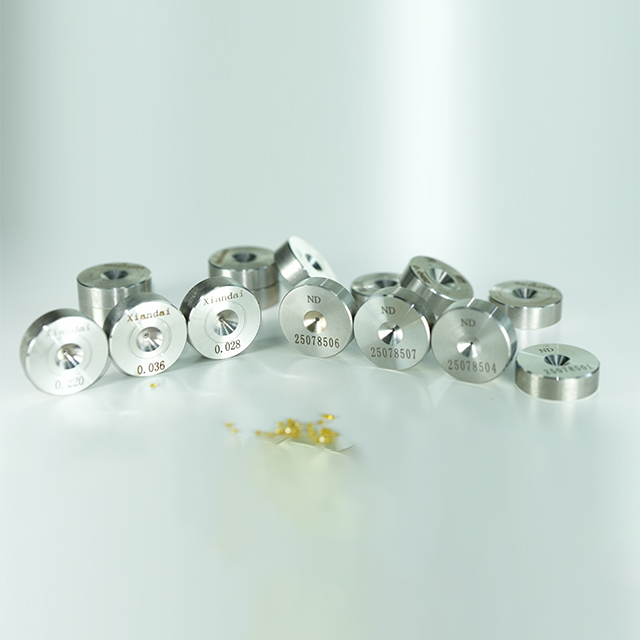
Die Selection Dictates Quality: The material and geometry of wire drawing dies (e.g., Polycrystalline Diamond vs. Tungsten Carbide) are the primary variables controlling copper wire surface finish and gauge accuracy.
Multi-Pass Efficiency: Achieving ultra-fine gauges requires a calculated, multi-step cold-drawing process that manages work hardening and thermal stress without compromising the wire's structural integrity.
Lubrication and Filtration are Non-Negotiable: Proper pretreatment, continuous lubrication, and the active filtration of copper fines are critical to mitigating die wear and preventing galling.
Inline Annealing Completes the Process: Cold drawing increases tensile strength at the cost of conductivity and ductility; inline continuous annealing is required to restore electrical properties.
Defect Mitigation Drives ROI: Standardized inspection of dies, wear-ring management, and real-time monitoring of drawing tension are required to prevent wire breakage and costly production downtime.
Table of Contents
The process typically begins with 8mm continuously cast copper rods. The quality of this starting material sets the baseline for the entire operation. Manufacturers generally choose between Electrolytic Tough Pitch (ETP) and Oxygen-Free (OF/OFE) copper. ETP copper contains trace amounts of oxygen, which can slightly affect ductility. Oxygen-Free copper provides superior ductility and electrical conductivity.
Chemical purity directly impacts drawing friction. Impurities in the copper matrix create hard spots that increase friction as the metal passes through the Wire Drawing Dies. High-purity copper reduces this friction, enhancing ductility and significantly extending the life expectancy of the tooling. Poor quality rod leads to frequent wire breaks and rapid die wear, regardless of downstream optimization.
Copper Type | Oxygen Content | Ductility | Impact on Tooling Wear |
|---|---|---|---|
Electrolytic Tough Pitch (ETP) | 0.02% - 0.04% | Standard | Moderate wear rate due to trace oxides |
Oxygen-Free (OF/OFE) | < 0.001% | High | Lower friction, extended die lifespan |
Before the copper rod enters the drawing machine, surface preparation is mandatory. The raw rod often carries surface oxides, scale, and minor physical defects from the casting and rolling process. If these contaminants enter the drawing dies, they act as abrasives, destroying the internal geometry of the die and scratching the wire surface.
Facilities utilize chemical cleaning, known as pickling, or mechanical descaling methods. Pickling uses acid baths to dissolve oxides, leaving a clean surface. Mechanical descaling physically removes the outer layer. Effective surface preparation directly correlates with downstream die longevity. Clean copper ensures the drawing lubricant can form a proper film, reducing metal-to-metal contact.
Inspect incoming 8mm copper rod for severe surface gouges or casting defects.
Run the rod through a mechanical descaling unit to break off loose oxide scale.
Pass the rod through a chemical pickling bath to dissolve remaining microscopic oxides.
Rinse and dry the rod thoroughly to prevent chemical carryover into the drawing lubricant.
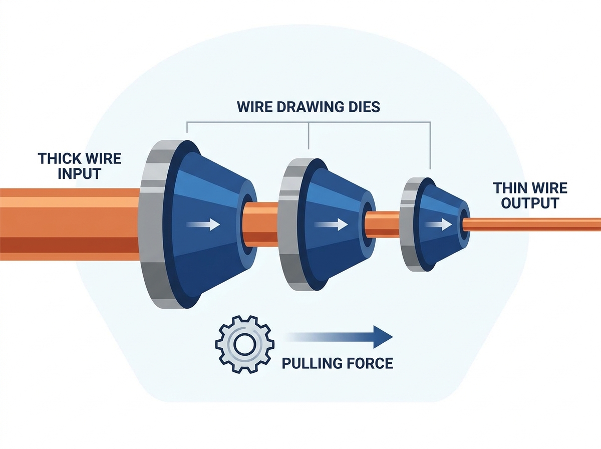
Cold drawing relies on plastic deformation. The machine pulls the copper rod through a tapered opening in the die. This action reduces the cross-sectional area of the metal while simultaneously increasing its length. The process occurs at room temperature, hence the term "cold working."
This physical deformation alters the internal grain structure of the copper. Cold drawing inherently increases the tensile strength of the metal, a phenomenon known as work hardening. As the copper becomes stronger, it also becomes less ductile and more brittle. Managing this work hardening is essential to prevent the wire from snapping during subsequent drawing passes.
Reducing an 8mm rod to fine wire cannot happen in a single step. The process requires sequential drawing stages: rod breakdown, intermediate drawing, fine drawing, and sometimes ultra-fine drawing. Each stage utilizes a series of dies with progressively smaller hole diameters.
Engineers calculate the area reduction per pass carefully. For copper, this reduction typically ranges from 20% to 26% per die. Exceeding the material's tensile limits by attempting too much reduction in one pass causes immediate breakage. A balanced multi-pass sequence distributes the deformation stress evenly, allowing for continuous, high-speed production without compromising the wire's structural integrity.
Because cold drawing severely work-hardens the copper, decreasing its electrical conductivity and ductility, annealing is an essential post-drawing step. Annealing applies controlled heat to recrystallize the copper grain structure, restoring its original softness and conductive properties.
Modern production lines utilize inline electric resistance annealers. These systems pass an electrical current directly through the moving wire, heating it rapidly. To prevent oxidation at high temperatures, the heating occurs within a protective nitrogen or steam atmosphere. The wire is then quenched and cooled before spooling, resulting in bright, highly conductive copper ready for stranding or insulation.
The internal geometry of a die dictates how the copper deforms. The entrance zone guides the wire and draws lubricant into the die. The approach angle is where the actual reduction occurs. For copper, this angle typically ranges from 16 to 18 degrees. Matching the approach angle to the specific reduction ratio and lubrication type ensures smooth metal flow and minimizes drawing force.
The bearing area determines the final diameter and ensures the roundness of the wire. It is a straight cylindrical section following the approach angle. The length of the bearing manages the development of the "wear ring," which is the groove worn into the die at the initial point of wire contact. A properly designed exit cone then allows the wire to leave the die without scraping, releasing elastic tension smoothly.
Die Zone | Primary Function | Typical Specification for Copper |
|---|---|---|
Entrance Bell | Guides wire, channels lubricant | Wide, smooth radius |
Approach Angle | Plastically deforms the wire | 16 - 18 degrees |
Bearing Length | Sets final diameter and roundness | 30% - 50% of wire diameter |
Exit Cone | Prevents scraping upon exit | 60 - 90 degrees |
Choosing the right material for Wire Drawing Dies is a major operational decision. Tungsten Carbide is the standard for high-impact rod breakdown and larger diameters. It is highly resistant to physical shock and handles the heavy deformation forces of initial reduction well. However, it experiences rapid abrasive wear compared to diamond materials.
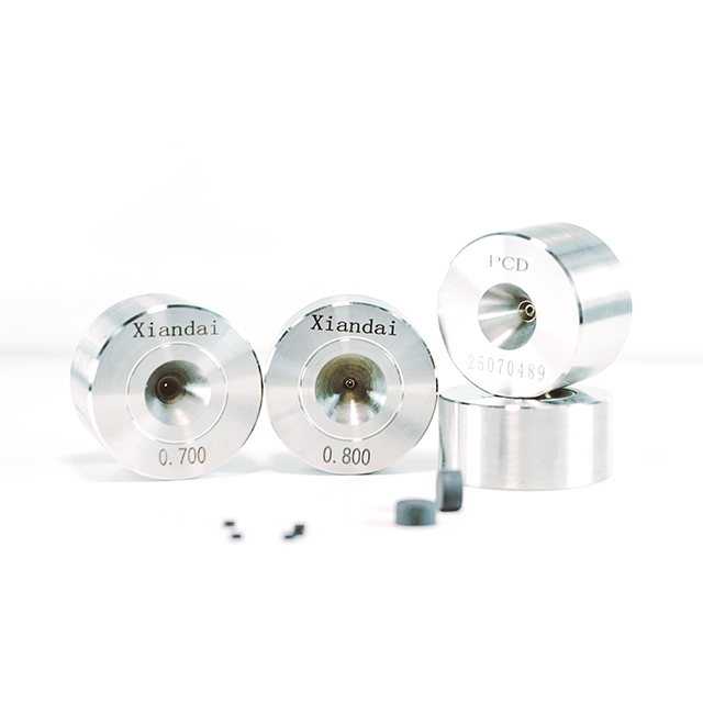
Polycrystalline Diamond (PCD) is essential for intermediate to ultra-fine copper wire. PCD offers superior hardness, exceptional wear resistance, and uniform thermal conductivity. While PCD carries a higher initial tooling investment, its extended lifespan and ability to maintain tight tolerances over long production runs make it indispensable for finer gauges.
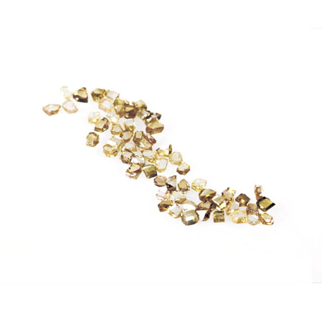
For drawing microscopic copper wire, typically below 0.05mm, manufacturers turn to Natural Diamond Dies (NDD) and Single-Crystal Synthetic Diamond (SCD). These niche applications require tooling that can produce flawless surfaces at microscopic scales.
NDD and SCD lack the grain boundaries found in PCD. This absolute crystal orientation allows for the creation of exceptionally smooth die surfaces. These materials are required for achieving mirror-like surface finishes and extreme gauge tolerances on ultra-fine wire, where even the slightest surface imperfection causes the wire to break under drawing tension.
High-speed drawing generates immense friction and deformation heat. Modern multi-wire machines can operate at speeds up to 40 m/s or higher. If unmanaged, this heat degrades the copper's metallurgical properties and destroys the die. Effective thermal management is a primary success criterion for high-speed operations.
Facilities evaluate cooling systems to maintain optimal operating temperatures. Submerged drawing machines keep the dies and capstans completely immersed in lubricant, providing excellent cooling. High-pressure spray cooling systems target the dies directly. Both methods aim to dissipate heat rapidly, protecting the wire surface and extending the life of the Wire Drawing Dies.
Drawing emulsions, typically water-soluble synthetic or semi-synthetic oils, reduce friction and cool the process. Proper emulsion concentration, temperature control, and pH balance are mandatory. If the emulsion breaks down, friction spikes, leading to immediate wire surface damage and die failure.
Continuous centrifugal filtration of abrasive copper dust and fines is equally important. As copper is drawn, microscopic particles flake off. If these fines remain in the lubricant, they act as a lapping compound, accelerating die wear and scratching the wire. Active filtration directly prevents premature die wear and ensures a clean, smooth wire finish.
Multi-pass capstan drives require significant power. Evaluating the energy consumption of these machines impacts overall operational efficiency. Manufacturers compare slip-type and non-slip drawing machines. In slip-type machines, the wire slips on the capstan to balance speed differences between drawing stages. This slipping generates additional friction and wear.
Non-slip machines utilize individually driven capstans that synchronize speeds precisely, eliminating wire slip. This design improves energy efficiency and ensures consistent wire tension. Consistent tension reduces the wear rate on the dies and minimizes the risk of wire breakage, making non-slip machines highly desirable for modern, efficient production lines.
Frequent wire breaks disrupt production and signal underlying process issues. Root causes often include copper rod oxide inclusions, incorrect die approach angles, or a failure in the lubrication film. Identifying these implementation risks quickly is vital for maintaining throughput.
Galling occurs when mechanical cold welding transfers copper directly onto the die surface. Chatter marks appear as rhythmic indentations on the wire. Both defects signal immediate process failure, usually due to poor lubrication or excessive drawing speed. Addressing these issues requires immediate inspection of the lubricant system and the condition of the dies.
Understanding die wear pattern progression helps establish effective maintenance cycles. Wear typically begins at the entry point, progresses to bearing wear, and can end in catastrophic chipping if ignored. Establishing a predictive framework for routine die inspection using microscopes and optical profile measurement tools is a strong mitigation strategy.
Facilities must evaluate the economics of die refurbishment. Recutting and repolishing a worn die to size it up to the next gauge is often more cost-effective than purchasing new tooling. A structured maintenance program maximizes the usable life of every die, reducing overall tooling expenditures.
Rigorous testing post-drawing and post-annealing ensures compliance with global standards. Manufacturers must track specific metrics to verify product quality. These metrics include elongation percentage, tensile strength, electrical resistivity measured on the IACS scale, and strict dimensional roundness.
Different applications require different standards. Hard-drawn copper wire must meet standards like ASTM B1, while soft or annealed copper wire follows ASTM B3. Flexible conductors often adhere to IEC 60228. Consistent quality control processes guarantee that the finished wire meets the exact specifications required by the end-user.
Evaluating the true value of tooling requires looking beyond the initial purchase price. A framework for calculating tooling efficiency should factor in the tonnage of copper drawn per die. A cheaper die that fails quickly costs more in downtime and replacement than a premium die that runs reliably for months.
Tracking lifespan metrics allows facilities to make informed purchasing decisions. By measuring the exact output achieved before a die requires recutting, manufacturers can determine which tooling provides the best return on investment for their specific drawing machines and copper grades.
Choosing between OEM and aftermarket tooling involves significant trade-offs. Low-cost aftermarket dies often present risks such as inconsistent internal geometry, poor diamond-to-carbide interface bonding, and premature wear. These inconsistencies lead to unpredictable production runs and higher scrap rates.
Partnering with established tooling manufacturers provides distinct advantages. Reputable suppliers offer custom die profiling, matching casing sizes, and technical engineering support. This support ensures the dies are optimized for the specific machinery and production goals, resulting in a more stable and efficient drawing process.
Achieving consistent, high-speed production of precision copper wire requires absolute control over every stage of the drawing line. Maintaining optimal wire quality and minimizing downtime depends heavily on high-durability, precision-engineered tooling; XIANDAI is a leading professional manufacturer specializing in advanced diamond and tungsten carbide wire drawing dies, dedicated to providing international customers with customized tooling solutions that maximize drawing efficiency and service life.
Establish a strict optical inspection schedule for all drawing dies to catch wear rings before they cause wire breakage.
Upgrade emulsion filtration systems to actively remove abrasive copper fines, extending die lifespan and improving surface finish.
Transition to non-slip drawing machinery where feasible to reduce energy consumption and maintain consistent wire tension.
Implement inline continuous resistance annealing to ensure the final product meets all electrical conductivity requirements.
Track the tonnage of copper drawn per die to accurately measure tooling lifespan and optimize supplier selection.
A: Wire breakage is typically caused by inclusions or oxides in the raw copper rod, incorrect die approach angles, excessive reduction ratios per pass, or a failure in the lubrication system that leads to high friction and thermal stress.
A: Dies should be inspected visually and with optical profile measurement tools at regular intervals, often weekly or after a specific tonnage of copper has been drawn, to identify wear rings before they cause surface defects or wire breaks.
A: Tungsten Carbide is highly impact-resistant and used for initial rod breakdown, but wears faster. Polycrystalline Diamond (PCD) is much harder, offers superior wear resistance, and is essential for maintaining tight tolerances in intermediate and fine wire drawing.
A: Cold drawing work-hardens the copper, increasing tensile strength but significantly reducing ductility and electrical conductivity. Inline annealing applies heat to recrystallize the metal, restoring the softness and conductivity required for electrical applications.
A: Poor lubrication increases friction, which generates excessive heat. This leads to rapid die wear, galling (copper welding to the die), chatter marks on the wire, and ultimately, frequent wire breakage and production downtime.
A: Yes, worn dies can often be refurbished. The process involves recutting and repolishing the internal geometry to size the die up to the next larger gauge, which is a cost-effective alternative to purchasing new tooling.