Views: 0 Author: Site Editor Publish Time: 2026-03-20 Origin: Site


The PCD drawing die is a game-changer in wire manufacturing, offering unmatched precision and durability compared to traditional dies. Understanding its processing methods is key for anyone aiming to produce high-quality wires consistently. From transparent diamond machining to sintered block and inlay techniques, each method impacts performance, surface finish, and die longevity. In this guide, we’ll break down how these methods work, their ideal applications, and tips to optimize your PCD wire drawing dies for both small and large-diameter wires.
The way a PCD wire drawing die is made can make a huge difference in how it performs. It affects precision, durability, and even the surface finish of the drawn wire. A die that isn’t processed properly may wear unevenly, cause friction, or produce rough surfaces. They also face challenges during machining. PCD is extremely hard, so standard tools can’t cut it easily. Holding tiny diamonds in place can be tricky, and grinding them requires careful control. Even slight mistakes in angle or pressure can create defects.
Here’s what usually gives engineers headaches:
Fixing small diamond particles for machining.
Maintaining exact hole size while grinding.
Avoiding cracks or chips during processing.
Several things determine how well a PCD die will work. Let’s break them down.
1. Diamond Particle Size and Quality
Smaller, uniform particles usually give smoother surfaces.
Impurities or uneven grains can reduce wear resistance.
2. Sintering Process and Material Bonding
Proper sintering bonds the diamond particles tightly.
Poor bonding may cause pieces to chip during drawing.
3. Tool Geometry and Finishing Techniques
The die’s shape controls wire flow and stress distribution.
Polishing and fine finishing reduce friction and prevent metal adhesion.
| Factor | Effect on Die Performance | Notes |
|---|---|---|
| Diamond Size | Surface finish, wear resistance | Smaller is usually better |
| Sintering Quality | Structural stability | Tight bonding prevents chipping |
| Die Geometry | Dimensional accuracy | Angles and taper are critical |
| Finishing | Friction, metal sticking | Polishing is essential |
By paying attention to these factors, manufacturers can create PCD dies that last longer, run smoother, and deliver better-quality wire.
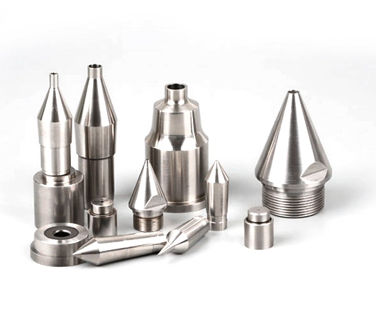
When it comes to PCD wire drawing dies, the way they are processed makes a big difference in performance. There are two main manufacturing methods, each suited for different die sizes and applications. Understanding these methods helps manufacturers choose the right approach for precision, durability, and efficiency.
This method involves machining directly on a transparent PCD die. One of the unique advantages is that we can actually see the hole being shaped, which helps ensure high precision.
Advantages of Transparent Diamond PCD Dies:
Real-time observation of the die hole during machining.
Easier to make minor adjustments to achieve exact wire diameters.
Ideal for producing high-precision diamond dies for fine wire applications.
Disadvantages:
Part of the diamond material must be ground away, which may slightly reduce tool life.
Tiny diamonds are difficult to secure during machining.
Requires skilled operators to avoid cracking or chipping the die.
Ideal Applications:
Best suited for small-diameter PCD die holes.
Commonly used for precision wire drawing dies in electronics or fine cable production.
Quick Comparison Table – Transparent Diamond Machining:
| Feature | Transparent Diamond PCD Die |
|---|---|
| Observation | Can monitor machining live |
| Diamond Loss | Moderate (grinding required) |
| Fixation | Difficult due to small diamond size |
| Best Use | Small-diameter wire drawing dies |
| Key Advantage | High precision and surface finish |
The second method starts by sintering diamond powders into blocks, which are then inlaid and machined into a PCD die. This method is widely used for larger diamond dies where stability and efficiency are more important than visibility.
Advantages of Sintered Block PCD Dies:
Retains about 2/3 to 4/5 of the diamond, reducing material waste.
Center of the die hole is easy to locate, improving machining accuracy.
Operation is more stable and convenient, especially for industrial wire drawing dies.
Disadvantages:
You cannot see the die hole forming during machining.
Requires precise alignment and measurement to achieve the desired hole dimensions.
Ideal Applications:
Mostly used for large-diameter PCD die holes.
Suitable for heavy-duty wire drawing dies for rods, cables, or industrial wires.
Quick Comparison Table – Sintered Block & Inlay:
| Feature | Sintered Block & Inlay PCD Die |
|---|---|
| Observation | Cannot see hole formation |
| Diamond Loss | Low (more retained) |
| Fixation | Stable and easy |
| Best Use | Large-diameter wire drawing dies |
| Key Advantage | Efficient, durable, less diamond waste |
Die size matters: Small-diameter wires → Transparent diamond machining; Large-diameter wires → Sintered block & inlay.
Precision vs efficiency: Transparent machining allows adjustments during production but may be slower. Sintered block method is faster and more stable for high-volume production.
Diamond die longevity: Retaining more diamond material helps extend the life of the PCD die.
Applications: Fine wires, electronics, and specialty cables often require small transparent PCD dies, while industrial rods and heavy wires need sintered block PCD dies.
By understanding these methods, manufacturers can choose the right approach to maximize the performance of PCD wire drawing dies, reduce downtime, and improve the quality of their wire products.
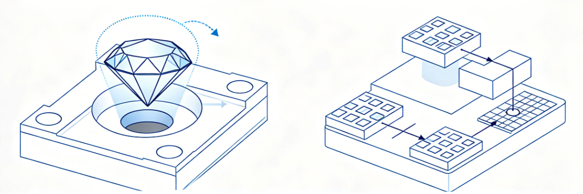
Even the best PCD wire drawing dies can develop defects over time. Understanding common issues helps us maintain performance and avoid unexpected downtime.
Some typical surface problems include:
Stripe marks on the die hole, caused by uneven wire flow.
Metal adhesion, where material sticks to the PCD die, increasing friction.
Elliptical wear of the die hole, leading to inconsistencies in wire diameter.
Increased sizing belt diameter, which reduces precision in drawn wires.
We can track these defects using simple inspection techniques. Small scratches or adhesion spots can become bigger problems if ignored.
| Defect | Cause | Effect on Wire |
|---|---|---|
| Stripe marks | Uneven wire drawing | Surface irregularity |
| Metal adhesion | High friction, material buildup | Increased wear |
| Elliptical wear | Die misalignment | Dimensional inconsistency |
| Sizing belt increase | Long-term use | Reduced precision |
PCD dies can often be re-sharpened multiple times to extend their lifespan. It’s a cost-effective way to maintain performance, especially for expensive diamond dies.
Key points about regrinding and reuse:
Process: Carefully grind the die hole to restore shape and remove surface defects.
Limits: Regrind until the diamond starts cracking. After that, it’s no longer safe or effective.
Impact: Proper regrinding maintains wire quality and reduces downtime, but too many cycles may slightly reduce precision.
Best Practices:
Inspect the die frequently for surface wear.
Regrind gradually, avoiding aggressive cuts.
Keep accurate records of the number of regrinds for each PCD die.
| Factor | Effect | Recommendation |
|---|---|---|
| Number of regrinds | Die longevity | Stop before diamond cracks |
| Grinding technique | Surface finish | Use precise, controlled grinding |
| Inspection frequency | Early defect detection | Check after each production batch |
| Die performance | Wire quality | Maintain consistent dimensions |
By monitoring surface defects and following regrinding best practices, we can get the most out of each PCD die, improving production efficiency while keeping costs lower.
Choosing the right PCD drawing die processing method directly affects your wire quality and production efficiency. Transparent machining works best for delicate, small-diameter dies, while sintered block and inlay methods excel in large-scale industrial applications. Keeping an eye on surface wear and following proper regrinding practices ensures longer die life and consistent output.
At NJ-ModernDiamond Co., Ltd., we provide expertly manufactured PCD wire drawing dies and professional technical support. Whether you’re producing fine wires or heavy industrial rods, our dies help you achieve precision, reliability, and efficiency every time.
A: Transparent machining allows real-time observation of the die hole but requires partial diamond grinding and precise fixation. Sintered block machining retains more diamond, is easier to fix, but the hole cannot be seen during processing.
A: PCD wire drawing dies last 15–25 times longer than tungsten carbide dies due to superior hardness and wear resistance.
A: Yes, they can be carefully re-sharpened multiple times until the diamond cracks, maintaining performance and extending die life.
A: Transparent machining is ideal for small-diameter dies, while sintered block and inlay machining suits large-diameter dies.
A: PCD’s hardness and smooth surface reduce friction, preventing metal adhesion and producing wires with high dimensional accuracy and polished finish.