Views: 0 Author: Site Editor Publish Time: 2026-07-21 Origin: Site


The efficiency, lifespan, and energy conversion capabilities of electric motors, transformers, and generators rely entirely on magnet wire. Precise dimensional and electrical tolerances dictate how well these components interchange electrical and magnetic energy on the shop floor and in the field. Surface defects, inconsistent enamel adhesion, or improper grain structure in the wire inevitably lead to dielectric failure. These flaws cause electrical shorts and result in catastrophic product recalls for heavy-duty machinery. Mitigating these operational risks requires a deep understanding of the end-to-end manufacturing process. You must control everything from the initial cold deformation utilizing precision Wire Drawing Dies to the final curing stages. This knowledge is mandatory whether you are evaluating a new wire supplier or optimizing an internal production line. Every micron of deviation in the bare wire translates to massive performance drops in the final wound coil.
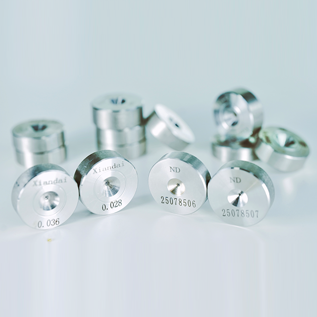
Precision Starts at the Die: The quality, material, and geometry of wire drawing dies dictate the bare wire's surface finish, which directly impacts the success of subsequent enamel application.
Shaping Dictates Application: While round wire relies heavily on traditional wire drawing dies, rectangular and square magnet wires require specialized rolling and profiling processes to maximize winding window density.
Thermal Restoration is Non-Negotiable: Annealing is required to reverse the cold deformation caused during drawing, restoring the necessary conductivity and flexibility to the copper or aluminum.
Concentricity and Insulation Coverage Determine Reliability: Whether using liquid enamel, extruded polymers, or protective coverings (fiberglass/tape), insulation must be applied with perfect uniformity to prevent high-voltage breakdown.
Supplier Evaluation Requires Process Transparency: Buyers must evaluate magnet wire suppliers based on their tooling maintenance schedules, curing oven controls, and adherence to NEMA/IEC testing standards.
Table of Contents
Magnet wire serves as the core component in electromagnetic coils. It converts electrical energy into a magnetic field and vice versa. The cross-sectional area directly determines current-carrying capacity. Material purity in copper and aluminum dictates overall electrical efficiency. High purity minimizes resistance-induced heat losses during continuous operation. Heat generation degrades insulation over time and shortens equipment lifespan. Manufacturers must maintain strict dimensional control to optimize this energy interchange. When operators run winding machines, any variation in the wire's diameter changes the resistance profile of the entire coil. This leads to hot spots. Hot spots burn through the enamel and cause immediate motor failure. You need absolute consistency from the rod breakdown stage all the way to the final spool.
To achieve this, plant managers monitor the conductivity ratings of incoming copper and aluminum rod. Oxygen-free high thermal conductivity (OFHC) copper is often the baseline for high-performance applications. The drawing process must not introduce impurities or alter this baseline conductivity. Lubrication systems must filter out microscopic metal fines that could embed into the wire surface. If conductive fines embed into the wire, they create a bridge through the insulation layer. This bridge guarantees a short circuit when the motor powers up. Maintaining the interchange efficiency requires a pristine manufacturing environment and rigorous quality control at every single step.
High-performance applications demand strict baseline requirements for conductivity and tensile strength. Electric vehicle motors and aerospace transformers operate under extreme stress. The wire must withstand rapid temperature fluctuations and intense mechanical vibration. Dimensional uniformity prevents winding issues during high-speed automated motor assembly. Inconsistent wire diameters cause tension spikes in winding machines. These spikes stretch the wire, alter its resistance, and damage the insulation layer. When a high-speed needle winder pulls wire into a stator slot, it applies significant mechanical force. If the wire is out of tolerance, it will either snap or scrape against the steel laminations.
Mechanical tolerances also dictate how well the wire packs into the winding window. Engineers design motors with a specific slot fill factor in mind. If the wire is oversized by even a few microns, the final turns will not fit into the slot. The operator will have to force the wire, damaging the enamel. If the wire is undersized, the coil will be loose. Loose coils vibrate during operation, causing mechanical wear on the insulation until it fails. You must hold dimensional tolerances to exact specifications using high-quality tooling.
A flawless bare wire surface guarantees the dielectric strength of the final product. Insulation layers bond effectively only to smooth, clean metal. Any micro-abrasions prior to insulation application will trap air. These abrasions cause uneven coating and lead to destructive pinholes. Pinholes act as weak points where high-voltage electrical arcing occurs. Maintaining surface integrity requires pristine tooling and continuous lubrication filtration. When you inspect bare wire under a microscope, it should look like a mirror. Any scoring, chatter marks, or drawing lines indicate a problem with the dies or the drawing lubricant.
The adhesion of the enamel depends entirely on the surface energy of the bare wire. If the surface is contaminated with residual drawing lubricants or oxides, the enamel will not wet properly. It will bead up, leaving areas of the wire exposed. This is why the cleaning and annealing stages are so critical. They prepare the surface for the chemical bond required between the metal and the polymer. A poor surface finish cannot be fixed by applying more enamel. The underlying defect will always compromise the final dielectric strength.
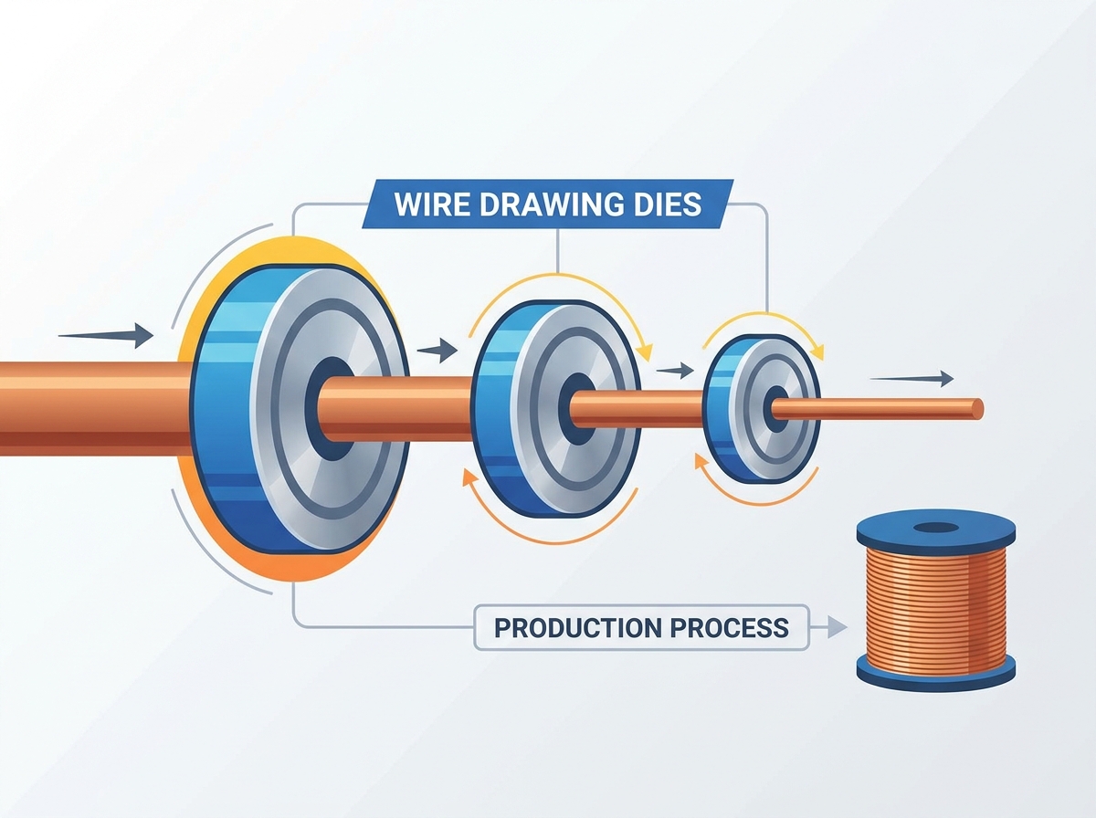
The manufacturing process begins by pulling copper or aluminum rod through progressively smaller dies. This mechanical process reduces the rod to the target wire diameter. Cold deformation significantly alters the metal's internal grain structure. The material experiences severe work hardening and a complete loss of ductility. The wire becomes brittle and highly resistant to further bending. Operators must carefully manage reduction ratios to prevent wire breakage during this stage. A typical multi-wire drawing machine might use 15 to 25 consecutive dies to reach the final size. Each die takes a specific percentage of the cross-sectional area.
If the reduction ratio is too aggressive, the wire will snap inside the machine. This causes massive downtime as operators must re-string the entire machine. If the reduction is too light, the machine requires too many dies, increasing tooling costs and machine footprint. The drafting schedule must be mathematically perfect. It must account for the work hardening rate of the specific alloy being drawn. Copper hardens differently than aluminum. The die sequences must reflect these metallurgical realities to maintain continuous, high-speed production.
Round wire production relies on traditional drawing processes. Rectangular and square magnet wires require specialized rolling and profiling techniques. Flat profiles maximize the slot fill factor in high-power motors and transformers. Higher slot fill increases magnetic density and overall motor efficiency. Turk's head rolls and specialized shaping dies maintain sharp corners. They ensure precise dimensions on rectangular profiles without compromising the metal's structural integrity. Rolling mills use driven rollers to flatten the round wire into a rectangular shape. This process is much gentler on the metal than drawing it through a square die.
However, rolling alone cannot produce the exact corner radii required for magnet wire. Sharp corners will cut through the enamel during winding. Therefore, the rolled wire passes through a final shaping die to radius the corners perfectly. This combination of rolling and drawing produces the optimal rectangular profile. The setup requires immense skill from the operator. The rollers must be perfectly aligned. Any misalignment will cause the wire to twist or form a trapezoidal shape instead of a true rectangle. This ruins the slot fill factor and forces the entire spool to be scrapped.
Selecting the right die material is critical for maintaining surface quality and production speed. Manufacturers choose between several distinct materials based on specific application needs. You must match the tooling to the metal and the production volume.
Die Material | Best Application | Key Advantage | Limitations |
|---|---|---|---|
Polycrystalline Diamond (PCD) | High-volume copper and aluminum drawing | Exceptional wear resistance and long lifespan | Higher initial procurement cost |
Natural Single-Crystal Diamond | Ultra-fine wire production | Produces the smoothest possible surface finish | Prone to cleavage if subjected to shock |
Tungsten Carbide | Initial rod breakdown stages | High impact resistance for heavy deformation | Wears faster than diamond materials |
You must base your die selection on the target wire diameter. Consider the metal type and the required production volume. High-volume runs justify the investment in premium PCD tooling. Short runs or heavy rod breakdown often utilize tungsten carbide. When drawing abrasive alloys, PCD is the only viable option. Natural diamond is reserved for the final finishing dies on ultra-fine wire machines, where surface finish is paramount and the drawing forces are relatively low.
The internal geometry of a drawing die controls wire tension and surface smoothness. The entrance zone guides the wire and draws in lubrication. The reduction angle performs the actual cold deformation. The bearing length dictates the final diameter and surface finish. The exit cone prevents mechanical scraping as the wire leaves the die. Continuous lubrication filtration prevents die wear and metal fines buildup. Dirty lubrication causes severe wire scoring and ruins the bare wire surface. You must inspect the die geometry regularly using laser measurement tools.
If the reduction angle is too wide, the drawing force increases, leading to wire breaks. If the angle is too narrow, the lubrication cannot enter the deformation zone, causing the wire to gall and weld to the die. The bearing length must be perfectly cylindrical. A tapered bearing will cause the wire diameter to fluctuate. The transition between the reduction angle and the bearing must be perfectly blended. Any sharp edge in the die profile will shave the wire, creating metal dust that contaminates the entire drawing system. Proper die maintenance is the foundation of wire quality.
Inline or batch annealing uses controlled heat to recrystallize the metal. This thermal process reverses the hardening caused by the drawing and rolling mills. Annealing restores the necessary ductility and electrical conductivity. The wire must achieve specific target elongation metrics. Proper elongation allows the wire to survive automated winding machines without snapping. Under-annealed wire remains brittle, while over-annealed wire stretches too easily under tension. Inline annealers use electrical current passed directly through the wire to heat it instantly. This allows for continuous production at high speeds.
Batch annealing involves placing entire spools of wire into a massive bell furnace. This process takes hours but provides very uniform grain structure for heavy rectangular wire. The choice between inline and batch depends on the wire size and the plant layout. Regardless of the method, the temperature profile must be exact. Copper recrystallizes at a specific temperature. If you miss that window, the wire will fail the elongation tests in the quality control lab. Operators must constantly monitor the voltage and current on inline annealers to ensure consistent heat input as line speeds fluctuate.
Copper and aluminum oxidize rapidly when exposed to high heat and oxygen. Annealing systems use steam or inert nitrogen atmospheres to prevent oxidation. This controlled environment maintains a clean, reactive surface for insulation bonding. Following the heat cycle, a water quenching process rapidly cools the wire. High-velocity air wipes then dry the wire completely. This prepares the bare metal for immediate insulation application without contamination. If oxygen enters the annealing chamber, the copper turns black with cupric oxide.
Enamel will not stick to oxidized copper. The entire run will fail the peel test. Steam is the most common protective atmosphere because it is cheap and effective. The steam displaces the oxygen in the annealing tube. The water quench must be turbulent to break up the steam blanket that forms around the hot wire. This ensures rapid and uniform cooling. The air wipes must remove 100% of the moisture. Any water droplets carried into the enamel applicator will cause blisters and massive pinhole failures in the final insulation layer.
Traditional liquid enamel application involves coating the wire in a polymer varnish. Modern applications often utilize extruded polymer coatings like PEEK, PPS, or PI. Extruded polymers serve high-temperature, high-frequency electric vehicle applications. Selection depends strictly on thermal class requirements and chemical resistance. You must also evaluate the required breakdown voltage for the specific motor design. Extruded coatings offer superior mechanical toughness compared to standard liquid enamels. They can withstand the aggressive winding techniques used in modern hairpin stators.
Liquid enamels are applied using applicator dies or felt wipes. The varnish is dissolved in a solvent. The wire passes through the varnish, then through a sizing die that meters the exact thickness of the wet film. Extrusion uses a crosshead die to melt and form a solid polymer tube around the wire. Extrusion eliminates the need for solvents, making it more environmentally friendly. However, extrusion equipment is expensive and requires precise temperature control to prevent polymer degradation. The choice between liquid and extruded depends on the end-user's exact specifications.
The covering process wraps the wire with protective physical layers. Common serving materials include glass fiber, Nomex, paper, or polyimide tape. Covered wire serves large-scale power transformers and heavy-duty industrial generators. These applications require extreme mechanical and thermal protection. The physical serving prevents short circuits during massive power surges. It also protects the conductor from abrasive damage during heavy manual winding. The taping heads must maintain constant tension on the serving material.
If the tape tension is too loose, the covering will bunch up and jam in the transformer slots. If the tension is too tight, the tape will snap during production. Glass fiber covering often involves a secondary varnish dip to bond the fibers together and to the wire. Paper covering is used extensively in oil-filled transformers because the paper absorbs the dielectric oil, creating a massive insulation barrier. The serving process is slower than enameling but provides mechanical protection that thin liquid films simply cannot match.
Liquid enamel is applied in multiple very thin layers rather than one thick coat. Manufacturers typically use 10 to 30 individual passes. Thin layers prevent solvent entrapment and ensure thorough curing. Applicator dies or felt wipes control the enamel thickness on each pass. This multi-pass method ensures strict concentricity across the wire profile. Uniform insulation thickness prevents weak spots and guarantees consistent dielectric strength. If you try to apply the enamel in one thick coat, the outside will cure while the inside remains liquid.
The trapped solvent will eventually boil, creating massive blisters and craters in the insulation. Multi-pass coating builds the insulation layer gradually. Each pass adds just a few microns of build. The wire travels up and down through the oven multiple times. The applicator dies must be perfectly aligned with the wire path. If the wire rubs against the side of the die, the coating will be eccentric. Eccentric wire has thin spots that will fail the high-voltage breakdown test. Concentricity is the ultimate measure of a well-run enameling line.
The coated wire travels through vertical or horizontal thermal curing ovens. The heat drives off the liquid solvents and initiates polymerization. The enamel cross-links to form a solid, durable, and flexible insulation layer. Temperature control within the oven is absolutely critical. Incorrect temperatures lead to under-cured or over-cured insulation. Both conditions compromise the wire's ability to withstand automated winding stresses. Modern ovens use catalytic oxidizers to burn the evaporated solvents, generating heat to sustain the oven temperature.
The oven is divided into multiple temperature zones. The bottom zone evaporates the solvent gently to prevent blistering. The middle zone initiates the cross-linking reaction. The top zone completes the cure and bakes the enamel to its final hardness. Operators must adjust the zone temperatures based on the line speed and the specific enamel chemistry. A wire that is under-cured will fail the solvent resistance test. A wire that is over-cured will fail the flexibility test and crack when bent around a mandrel.
Maintaining precise, automated tension during the final spooling process is vital. Excessive tension stretches the newly annealed wire. Stretching alters the final diameter and increases electrical resistance. Poor spooling tension can also damage the fresh enamel layer. Automated traverse guides ensure the wire lays flat on the spool. Proper spooling prevents tangles and snags during the end-user's winding operations. The spooling machine uses dancer arms or load cells to monitor the wire tension continuously.
If the tension drops, the wire will loop and tangle on the spool. If the tension spikes, the wire will bury itself into the underlying layers. When the customer tries to unwind a buried wire, it will snag and snap, shutting down their winding machine. The traverse mechanism must reverse direction instantly at the flanges of the spool. Any delay will cause the wire to pile up against the flange, creating a massive tangle. Perfect spooling is the final quality check before the wire ships to the customer.
Standard high-voltage continuity tests detect microscopic flaws in the insulation. The wire passes through a high-voltage sponge or bead bath. The system records an electrical fault every time current breaches the insulation. High pinhole counts indicate severe upstream process failures. They point to worn tooling, incorrect curing temperatures, or inadequate cleaning before enameling. Continuous inline testing prevents defective wire from reaching the customer. You must set the test voltage according to the wire size and insulation build.
If the inline tester detects a fault, it triggers an alarm and marks the wire. The operator must investigate the root cause immediately. Is the bare wire surface scratched? Is an applicator die plugged with dried enamel? Is the oven temperature dropping? You cannot simply cut out the bad section and keep running. You must fix the process. In addition to inline testing, quality control labs perform destructive dielectric breakdown tests. They twist two wires together and apply increasing voltage until the insulation fails completely. This verifies the ultimate strength of the polymer film.
You must evaluate a supplier's compliance with global manufacturing standards. NEMA MW 1000 dictates strict requirements for thermal endurance and thermoplastic flow. It also covers springback limits and solvent resistance. Adherence to these standards guarantees baseline performance in the field. Request documented test results for every wire batch. Consistent compliance demonstrates strong internal process controls and reliable manufacturing practices. The standards dictate exactly how the tests must be performed.
For example, the thermoplastic flow test requires placing crossed wires under a specific load and heating them until they short out. This proves the enamel will not melt and flow away when the motor gets hot. The springback test measures the wire's dead softness. You wind the wire around a mandrel and measure how much it uncoils when released. High springback means the wire is not fully annealed and will be difficult to wind into tight coils. Demand full transparency and complete test reports from your suppliers.
Investing in premium PCD tooling presents a significant upfront cost. However, you must weigh this against machine downtime and frequent die replacement. Cheap tooling wears quickly and produces scrapped wire. Poor surface finish from worn dies ruins the subsequent enameling process. High-quality dies maintain tight tolerances over massive production volumes. The long-term production yield easily justifies the initial tooling investment. When you calculate the cost of a wire break on a high-speed tandem line, the price of a premium die becomes irrelevant.
A single wire break can cost hours of production time. The operator has to re-string the machine, scrap the partial spool, and restart the oven. Worn dies also cause the wire diameter to drift out of tolerance. You end up giving away free copper if the wire runs heavy, or you produce scrap if it runs light. Invest in the best tooling available and implement a strict die inspection and recutting program. This is the only way to maintain profitability in wire manufacturing.
Manufacturers constantly balance line speed against final insulation quality. Pushing wire through drawing, rolling, and enameling too fast compromises the process. High speeds reduce the time the wire spends in the curing oven. This leads to under-cured, tacky insulation that fails during winding. Conversely, running too slow can cause over-cured, brittle enamel. You must optimize line speeds to match the oven's thermal capacity. Every enamel chemistry has a specific cure window.
If you want to run faster, you need a longer oven or a more reactive enamel. You cannot simply turn up the heat. Excessive heat will burn the outside of the enamel before the inside cures. The line speed must also match the drawing machine's capability. If you draw the wire too fast, the lubrication will break down, and the dies will overheat. Finding the optimal line speed requires extensive process engineering and continuous monitoring of the final wire properties.
Auditing a magnet wire manufacturer requires strict attention to process controls. You should request comprehensive technical documentation during your evaluation. Review their tooling maintenance schedules and die inspection logs. Verify their atmospheric controls during the annealing process. Check their inline high-voltage continuity testing procedures. Process transparency is the only way to guarantee consistent wire quality. Walk the shop floor and look at the drawing machines.
Are the lubrication tanks clean? Are the operators measuring the bare wire diameter regularly? Look at the enameling ovens. Are the temperature controllers calibrated? Ask to see the scrap records. A high scrap rate indicates an unstable process. A reliable supplier will have documented procedures for every step of the manufacturing process and will be eager to show you their quality control data. Do not accept verbal assurances; demand hard data.
High-quality magnet wire is a highly engineered component, not a simple commodity. Every production step dictates the final electrical efficiency and equipment lifespan. The initial drawing and profiling stages demand absolute precision. Achieving this high level of precision requires reliable, high-performance wire drawing tooling engineered for strict dimensional control; XIANDAI is a trusted professional manufacturer specializing in advanced diamond and carbide wire drawing dies, providing global customers with durable tooling solutions that optimize wire surface quality and production yield. Buyers must prioritize suppliers who demonstrate rigorous maintenance of their tooling. Precise atmospheric controls during annealing and multi-pass enameling capabilities are essential. Take the following steps to ensure your magnet wire meets operational demands.
Request comprehensive technical data sheets for all wire profiles to verify dimensional tolerances.
Review the supplier's testing protocols against NEMA MW 1000 standards to ensure compliance.
Audit your internal tooling inventory to identify yield-loss culprits and replace worn dies immediately.
Implement continuous inline high-voltage continuity testing on all active production lines.
A: They perform the critical cold deformation that reduces the rod to the target diameter. Precision dies ensure exact dimensional tolerances and create a flawless surface finish. This smooth surface prevents micro-defects and guarantees uniform insulation adhesion during the enameling process.
A: Drawing involves pulling round wire through progressively smaller dies to reduce its diameter. Rolling passes the wire through specialized rolling mills and Turk's head rolls. Rolling produces flat, rectangular, or square profiles designed to maximize slot fill in high-power motors.
A: The initial drawing process causes severe cold deformation and work hardening. Annealing uses controlled heat to recrystallize the metal's grain structure. This thermal process restores the wire's ductility, flexibility for winding, and optimal electrical conductivity.
A: Enameled wire features a thin, liquid varnish coating cured in an oven. Covered wire is physically wrapped with materials like paper, glass fiber, or polyimide tape. Covering provides extreme thermal and physical protection for heavy-duty transformers and large industrial generators.
A: Pinholes occur when the insulation layer fails to coat the wire uniformly. They are caused by trapped air, dust contamination, or uneven enamel application. Surface abrasions from worn drawing dies also create microscopic peaks that puncture the thin enamel layer.
A: Choose Polycrystalline Diamond (PCD) for high-volume runs and abrasive materials due to its wear resistance. Select single-crystal natural diamond for ultra-fine wire requiring the smoothest surface finish. Use tungsten carbide dies for the initial heavy rod breakdown stages.